
User Manual


OPERATING MANUAL AND USER GUIDE
7
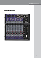
1
Mic
(XLR connector) Balanced input +4dB
2
Line:
Use this input for audio interfaces and other line level
devices
3
HPF:
High Pass Filter (24 dB/octave. –6dB @ 80 Hz & –
30dB @ 20 Hz) cuts low frequencies.
4.
Gain:
This allows you to calibrate the channel to different
sources and apply correct gain structure.
5
High EQ:
Centered at 12kHz. ±10dB of gain.
6
Mid EQ:
Centered at 1kHz. ±10dB of gain.
7
Low EQ:
Centered at 80Hz. ±10dB of gain.
8
Aux Pre:
Sends signal to the Aux output. It is post fader so
the output level changes with the Channel Volume level
9
FX:
Allows you to adjust the amount of the effect sent to an
external effects processor,
10
Pan:
Allows you to adjust the spatial placement of the
channel.
11
Peak LED
: This LED lights when the level of the input signal
is too high. It is a good practice to only allow this light to
icker, not constantly glow.
12
Level:
Adjust the level of the channel signal to the Main Mix
Level control.
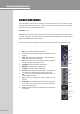
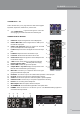
CONNECTIONS/WIRING
The SL424USB input panel has one XLR plus one TRS connector for each of the rst 4 channels
and TRS connectors for Channels 5–8. Be sure to use a high quality shielded cable with suitable
connectors when connecting balanced sources.
Channels 1 – 4:
Balanced XLR microphone and line inputs make it easy to plug microphones into the mixer. Plug in
your mics, making sure the output volume is low with PAN and all EQ controls in the center detent
position with GAIN controls all the way down.
For best results, the gain throughout the system should be matched from one device to the next.
1
2
3
4
5
6
7
8
9
10
11
12