
Operating instructions


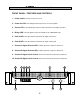

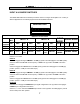


INPUT A & B MODE SWITCHES
The MODE SWITCHES for the S-2500 provide the means to configure the amplifier in for a variety of
different applications. The following legend shows the available selections.
7
Switch 1: is not used
INPUT A
Switch 2: Engages the signal LIMITER in the ON (up) position and disengages it when OFF (down).
Switch 3: Selects the LO CUT roll off frequency of 30Hz in the up position and 50Hz in the down
position.
Switch 4: Engages the LO CUT filter in the OFF (down) position and disengages it in the ON (up)
position. (This is a -12dB per octave filter slope).
INPUT B
Switch 5: Engages the signal LIMITER in the ON (up) position and disengages it when OFF (down).
Switch 6: Selects the LO CUT roll off frequency of 30Hz in the up position and 50Hz in the down
position.
Switch 7: Engages the LO CUT filter in the OFF (down) position and disengages it in the ON (up)
position. (This is a -12dB per octave filter slope).
OUTPUTS
Switches 8 & 9: Engage the PARALLEL input signal configuration in the up position and engages
STEREO input configuration when down.
Switch 10 , 11 & 12: Selects the BRIDGE output mode in the up position and disengages it (normal
stereo mode) in the down position.
S-SERIES Professional Amplifiers
MODE SWITCHES
ON
1 2 3 4 5 6 7 8 9 10 11 12
LO
CUT
LO CUT
LIMITER
INPUT A INPUT B
INPUT
MODE
BRIDGE MODE
SW4
SW3
SW2SW1
N/A
N/A
N/A
N/A
UP(ON)
DOWN
Switch
position
Engage
Disengage
30Hz
50Hz
SW10 SW11 SW12SW8 SW9
PARALLEL
STEREO
LO
CUT
LO CUT
LIMITER
SW7
SW6
SW5
Engage
Disengage
Engage
Disengage
Disengage
30Hz
50Hz
Engage
Disengage
Engage
INPUT
MODE
BRIDGE MODE
Switch Function