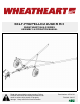
SELF-PROPELLED AUGER KIT WHEATHEART BH & R SERIES ASSEMBLY & OPERATION MANUAL Read this manual before using product. Failure to follow instructions and safety precautions can result in serious injury, death, or property damage. Keep manual for future reference.
WHEATHEART - SELF-PROPELLED AUGER KIT WHEATHEART BH & R SERIES This product has been designed and constructed according to general engineering standardsa. Other local regulations may apply and must be followed by the operator. We strongly recommend that all personnel associated with this equipment be trained in the correct operational and safety procedures required for this product. Periodic reviews of this manual with all employees should be standard practice.
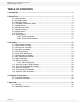
WHEATHEART - SELF-PROPELLED AUGER KIT WHEATHEART BH & R SERIES TABLE OF CONTENTS 1. Introduction .......................................................................................................................... 5 2. Safety First............................................................................................................................ 7 2.1. General Safety ......................................................................................................... 8 2.2.
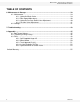
WHEATHEART - SELF-PROPELLED AUGER KIT WHEATHEART BH & R SERIES TABLE OF CONTENTS 6. Maintenance & Storage...................................................................................................... 6.1. Maintenance ........................................................................................................... 6.1.1. Hydraulic Winch Valve.............................................................................. 6.1.2. Ram Speed Adjustment............................................
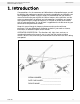
WHEATHEART - SELF-PROPELLED AUGER KIT WHEATHEART BH & R SERIES 1. INTRODUCTION 1. Introduction Congratulations. As the new owner of a Wheatheart self-propelled auger, you will be working with equipment especially designed to complement and improve your farming operation. Before using this auger, we recommend that you read this manual to familiarize yourself with the various features of the machine, and the necessary precautions for efficient and safe operation.
1.
WHEATHEART - SELF-PROPELLED AUGER KIT WHEATHEART BH & R SERIES 2. SAFETY FIRST 2. Safety First The Safety Alert symbol to the left identifies important safety messages on the product and in the manual. When you see this symbol, be alert to the possibility of personal injury or death. Follow the instructions in the safety messages. Why is SAFETY important to you? Three big reasons: • Accidents disable and kill. • Accidents cost. • Accidents can be avoided.
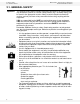
2. SAFETY FIRST 2.1. GENERAL SAFETY WHEATHEART - SELF-PROPELLED AUGER KIT WHEATHEART BH & R SERIES 2.1. GENERAL SAFETY Important: This general safety section includes instructions that apply to all safety practices. Any instructions specific to a certain safety practice (e.g., assembly safety), can be found in the appropriate section. Always read the complete instructional sections and not just these safety summaries before doing anything with the equipment.
WHEATHEART - SELF-PROPELLED AUGER KIT WHEATHEART BH & R SERIES 2. SAFETY FIRST 2.2. ASSEMBLY SAFETY • Follow good shop practices: • keep service area clean and dry • be sure electrical outlets and tools are properly grounded • use adequate light for the job at hand • Think SAFETY! Work SAFELY! 2.2. ASSEMBLY SAFETY • Read the instructions and familiarize yourself with the subassemblies and hardware making up the equipment. • The components are large, heavy, and can be hard to handle.
2. SAFETY FIRST 2.3. OPERATION SAFETY WHEATHEART - SELF-PROPELLED AUGER KIT WHEATHEART BH & R SERIES Figure 2.
WHEATHEART - SELF-PROPELLED AUGER KIT WHEATHEART BH & R SERIES 2. SAFETY FIRST 2.4. TRANSPORT & PLACEMENT SAFETY 2.4. TRANSPORT & PLACEMENT SAFETY • Before raising/lowering/moving the auger, make sure the area around the auger is clear of obstructions and/or unauthorized personnel. Never allow anyone to stand on or beneath auger while transporting or placing auger. • Wheels must be free to move when raising or lowering auger. • Do not stand between towing vehicle and grain auger when hitching.
2. SAFETY FIRST 2.5. STORAGE SAFETY WHEATHEART - SELF-PROPELLED AUGER KIT WHEATHEART BH & R SERIES 2.5. STORAGE SAFETY • Store in an area away from human activity. • Do not permit children to play on or around the stored machine. 2.6. MAINTENANCE SAFETY • Before applying pressure to a hydraulic system, make sure all components are secure, hoses are in good condition, and couplings are tightly connected and undamaged.
WHEATHEART - SELF-PROPELLED AUGER KIT WHEATHEART BH & R SERIES 2. SAFETY FIRST 2.8. ENGINE SAFETY • Before moving a hydraulic cylinder, ensure that the attached component is safely secured. WARNING Hydraulic fluid can cause serious injury if it penetrates the skin. If it does, see a doctor immediately. • Relieve pressure before disconnecting hydraulic line. • Wear proper hand and eye protection and use wood or cardboard, not hands, when searching for leaks. 2.8.
2. SAFETY FIRST 2.10. SAFETY DECALS WHEATHEART - SELF-PROPELLED AUGER KIT WHEATHEART BH & R SERIES 2. Decide on the exact position before you remove the backing paper. 3. Align the decal over the specified area and carefully press the small portion with the exposed sticky backing in place. 4. Slowly peel back the remaining paper and carefully smooth the remaining portion of the decal in place. 5. Small air pockets can be pierced with a pin and smoothed out using the sign backing paper. 2.10.2.
WHEATHEART - SELF-PROPELLED AUGER KIT WHEATHEART BH & R SERIES 3. ASSEMBLY 3.1. GEAR PUMP ASSEMBLY 3. Assembly Warning: Before continuing, ensure you have read and understand the relevant information in the safety section. Safety information is provided to help prevent serious injury, death, or property damage. CAUTION Ensure the auger is in the fully lowered position and on a level surface with the wheels chocked before proceeding with any assembly. 3.1. GEAR PUMP ASSEMBLY Refer to Figure 3.
3. ASSEMBLY 3.3. OIL RESERVOIR ASSEMBLY WHEATHEART - SELF-PROPELLED AUGER KIT WHEATHEART BH & R SERIES Figure 3.1 Gear Pump Installation Guard 3.3. OIL RESERVOIR ASSEMBLY 1. Bolt the double tank mount brackets to the frame with 3/8” x 2-5/8” u-bolts 3/8” washers and 3/8” nylock nuts (Figure 3.2). 2. Secure the 22L oil reservoir to the tank mount brackets using the 32” clamps provided.
WHEATHEART - SELF-PROPELLED AUGER KIT WHEATHEART BH & R SERIES 3. ASSEMBLY 3.4. GEAR DRIVE ASSEMBLY Figure 3.2 Hydraulic Reservoir Installation 3.4. GEAR DRIVE ASSEMBLY CAUTION Before removing the tires from the auger, ensure the auger is in the fully lowered position. Position the auger on a flat level surface and block the axle to fully support the auger while removing the wheels. 1. Remove tires from auger. 2. Insert ring gear into rim (Figure 3.3).
3. ASSEMBLY 3.5. OVER-CENTER DRIVE WHEATHEART - SELF-PROPELLED AUGER KIT WHEATHEART BH & R SERIES 3.5. OVER-CENTER DRIVE 1. Once the wheel is bolted to the hub, the over-center drive assembly can be installed. 2. Position the axle cap of the over-center drive assembly squarely on the axle tube as shown in Figure 3.4. Figure 3.5 Figure 3.4 3. With the pinion gear flush with the ring gear (Figure 3.6), bolt the axle cap to the axle tube. Figure 3.
WHEATHEART - SELF-PROPELLED AUGER KIT WHEATHEART BH & R SERIES 3. ASSEMBLY 3.6. PINION GEAR ADJUSTMENT 3.6. PINION GEAR ADJUSTMENT For gear depth alignment, refer to Figure 3.7. NOTICE Failure to ensure proper gear meshing will result in gear damage. The pinion gear should mesh with the ring gear to provide maximum tooth contact (Figure 3.6).
3. ASSEMBLY 3.7. UNDERCARRIAGE INSTALLATION Note: WHEATHEART - SELF-PROPELLED AUGER KIT WHEATHEART BH & R SERIES 4. In the location noted in Figure 3.8, bolt the control panel ring to the auger tube approximately to the measurements in Table 3.1. Do not tighten the bolts yet. The ram mount ring and the control ring normally get mounted together as one unit. The only exception are the 46’ and 51’ auger models. For these models, two extra tube half clamps are provided. 5.
WHEATHEART - SELF-PROPELLED AUGER KIT WHEATHEART BH & R SERIES 3. ASSEMBLY 3.8. RAM EXTENSION INSTALLATION Figure 3.9 Self-Propelled Auger Frame Installation 9. One end of the crossbrace is attached to the v-frame tab, the other is attached to the transport tube using clamp bands (Figure 3.9). 10. When attaching to the v-frame, be sure to mount one crossbrace to the top side of the v-frame tab, and the other to the bottom. 3.8.
3. ASSEMBLY 3.9. CABLE INSTALLATION WHEATHEART - SELF-PROPELLED AUGER KIT WHEATHEART BH & R SERIES Figure 3.10 Ram Extension Installation 3.9. CABLE INSTALLATION Important: Note: 1. Loop cable over top of drum, through hole in drum end, through cable clamp, and then tighten with two 3/8” set screws (Figure 3.12). Cable must enter winch on the top side of drum and must have a minimum of 3 wraps on the drum when auger is in the transport position. FOR NEW INSTALLATIONS, USE STEPS 2 AND 3 2.
WHEATHEART - SELF-PROPELLED AUGER KIT WHEATHEART BH & R SERIES 3. ASSEMBLY 3.10. WINCH ASSEMBLY Figure 3.11 3.10. WINCH ASSEMBLY Important: 1. Lower auger completely and remove the hand winch on the lower auger frame. 2. Place the winch on the frame as shown in Figure 3.12 using the measurement in Table 3.3. The hydraulic winch position should be adjusted until the drum is 1” away from the auger tube when in transport position. Use Table 3.3 to position winch. 3.
3. ASSEMBLY 3.11. HOSE KIT LAYOUT—NO BIN SWEEP WHEATHEART - SELF-PROPELLED AUGER KIT WHEATHEART BH & R SERIES Figure 3.12 Winch Positioning Table 3.3 Winch Positioning AUGER 8” x 51’ 8” x 36’ 10” x 36’ 10” x 46’ 10” x 41’ DIM 'A' 5-1/2" 3-3/4" 1/2" 5-7/8" 6-5/8" WARNING Falling auger hazard. To prevent serious injury or death while winching, ensure winch cable is fed onto the winch drum as shown above, and replace cable if frayed or damaged. 3.11. HOSE KIT LAYOUT—NO BIN SWEEP Refer to Table 3.
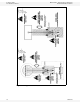
WHEATHEART - SELF-PROPELLED AUGER KIT WHEATHEART BH & R SERIES 3. ASSEMBLY 3.11. HOSE KIT LAYOUT—NO BIN SWEEP Figure 3.13 Wheatheart Hydraulic Schematic, SP Transport Kit without Bin Sweep Option Table 3.
3. ASSEMBLY 3.11. HOSE KIT LAYOUT—NO BIN SWEEP WHEATHEART - SELF-PROPELLED AUGER KIT WHEATHEART BH & R SERIES Table 3.4 Wheatheart Hydraulic Hose Lengths, SP Transport Kit without Bin Sweep Option Item G1,G2 H1,H2 H1,H2 H1,H2 H1,H2 I1 J1 Description Hose, HYD, 3/8 x 159, 6FJICS x 3/8MNPT, 1W Hose, HYD, 3/8 x 148, 6FJIC x 1/2MNPT, 1W Hose, HYD, 3/8 x 122, 6FJICS x 1/2MNPT, 1W Hose, HYD, 3/8 x 96.
WHEATHEART - SELF-PROPELLED AUGER KIT WHEATHEART BH & R SERIES 3. ASSEMBLY 3.12. HOSE KIT LAYOUT WITH BIN SWEEP 3.12. HOSE KIT LAYOUT WITH BIN SWEEP Refer to Table 3.5, Figure 3.15. SP TRANSPORT KIT INCLUDES: • hoses (A, B, E, F1, F2, G1, G2, H1, H2, I1, I2, J1, J2), winch valve, winch hoses (H1, H2) BIN SWEEP OPTION INCLUDES: • hoses (D, C, L, K), relief valve Figure 3.
3. ASSEMBLY 3.12. HOSE KIT LAYOUT WITH BIN SWEEP WHEATHEART - SELF-PROPELLED AUGER KIT WHEATHEART BH & R SERIES Table 3.
WHEATHEART - SELF-PROPELLED AUGER KIT WHEATHEART BH & R SERIES 3. ASSEMBLY 3.13. HOSE KIT ASSEMBLY 3.13. HOSE KIT ASSEMBLY Refer to Figures 3.11 - 3.16. Important: 1. Assemble hoses as illustrated. 2. Keep free of dirt while assembling. 3. Keep pressure and return sides aligned. 4. Tighten after being satisfied that the hoses are in the proper position. 5. Check operation. 6.
3. ASSEMBLY 3.14. CUSHION VALVE INSTALLATION WHEATHEART - SELF-PROPELLED AUGER KIT WHEATHEART BH & R SERIES 3.14. CUSHION VALVE INSTALLATION Connect the hoses as shown in Figure 3.17 and 3.18, ensuring that the hoses are not crossed. Connect the lower cushion block hoses to the lower ports on each hydraulic motor as shown. NOTICE Do not over-tighten fittings! Over-tightening hose fittings can crack the fittings or motor body and will void the warranty. Figure 3.17 Cushion Block Installation Figure 3.
WHEATHEART - SELF-PROPELLED AUGER KIT WHEATHEART BH & R SERIES 3. ASSEMBLY 3.15. HYDRAULIC FILTER INSTALLATION 3.15. HYDRAULIC FILTER INSTALLATION When connecting the hydraulic filter, make sure that it is properly installed. An arrow is engraved in the filter head indicating the direction of oil flow. The filter MUST be installed with the oil flowing in the same direction as the arrow indicates. The filter goes in the return line right before the tank. Figure 3.
3. ASSEMBLY 3.15.
WHEATHEART - SELF-PROPELLED AUGER KIT WHEATHEART BH & R SERIES 4. TRANSPORT & PLACEMENT 4.1. TRANSPORT PROCEDURE 4. Transport & Placement Warning: Before continuing, ensure you have read and understand the relevant information in the safety section. Safety information is provided to help prevent serious injury, death, or property damage. 4.1. TRANSPORT PROCEDURE Note: Use only a tractor or towing vehicle of adequate power and capacity to transport the machine.
4. TRANSPORT & PLACEMENT 4.2. PLACEMENT PROCEDURE WHEATHEART - SELF-PROPELLED AUGER KIT WHEATHEART BH & R SERIES 4.2. PLACEMENT PROCEDURE Follow this procedure when placing the machine into its working position: 1. Be sure there is enough clearance from overhead obstructions, power lines, or other equipment to move the machine into its working position. 2. Position machine in the desired area. For operating instructions, see Section 5.2. WHEN PLACING UNDER HOPPER BOTTOM BINS: 1.
WHEATHEART - SELF-PROPELLED AUGER KIT WHEATHEART BH & R SERIES 5. OPERATION 5.1. START-UP 5. Operation Warning: Before continuing, ensure you have read and understand the relevant information in the safety section. Safety information is provided to help prevent serious injury, death, or property damage. Operators must observe safety procedures at all times and follow the pre-operational checklist before each start-up.
5. OPERATION 5.2. OPERATING PROCEDURE WHEATHEART - SELF-PROPELLED AUGER KIT WHEATHEART BH & R SERIES AFTER OPERATING OR TRANSPORTING FOR 1/2 HOUR: • Retorque all wheel bolts (if applicable). • Retorque all fasteners and hardware. • Check all safety decals are installed and legible. Apply new ones if needed. • Check all guards are installed and working as intended. AFTER 3 HOURS: • Change oil for best results. AFTER 5 AND 10 HOURS: • Check all hydraulic hoses and fittings for leaks.
WHEATHEART - SELF-PROPELLED AUGER KIT WHEATHEART BH & R SERIES 5. OPERATION 5.2. OPERATING PROCEDURE Figure 5.1 Hydraulic Control Valve Decal Figure 5.
5. OPERATION 5.2.
WHEATHEART - SELF-PROPELLED AUGER KIT WHEATHEART BH & R SERIES 6. MAINTENANCE & STORAGE 6.1. MAINTENANCE 6. Maintenance & Storage Warning: Before continuing, ensure you have read and understand the relevant information in the safety section. Safety information is provided to help prevent serious injury, death, or property damage. 6.1. MAINTENANCE Before performing any maintenance on this unit, shut off and remove key or lock out power source. 1.
6. MAINTENANCE & STORAGE 6.1. MAINTENANCE WHEATHEART - SELF-PROPELLED AUGER KIT WHEATHEART BH & R SERIES WARNING Winch cable must be wound onto the drum of the winch from the top of the drum. This ensures the safe and proper operation of the hydraulic winch. 6.1.2. RAM SPEED ADJUSTMENT Ram speed is regulated at the control valve. The adjustable stroke limiter screws and lock nuts set the speed of ram travel individually in each direction (Figure 6.2).
WHEATHEART - SELF-PROPELLED AUGER KIT WHEATHEART BH & R SERIES 6. MAINTENANCE & STORAGE 6.2. STORAGE 3. To increase hydraulic pressure: repeat step 2. except turn adjustment screw in (clockwise) 1/4 turn. Tighten jam nut. 6.1.4. CUSHION VALVE ADJUSTMENT To control the speed of the mover, the adjustable needle valve (Figure 6.3) can be: • screwed in for increased speed (adjust by 1/8 turn increments) • screwed out for decreased speed (adjust by 1/8 turn increments) Figure 6.3 Cushion Valve Adjustment 6.
6. MAINTENANCE & STORAGE 6.2.
WHEATHEART - SELF-PROPELLED AUGER KIT WHEATHEART BH & R SERIES 7. TROUBLESHOOTING 7. Troubleshooting PROBLEM Valve is leaking. Machine operates slowly. CAUSE • • • • loose/cracked fittings worn hose valve spools are worn oil is hot SOLUTION • • • • • blockage in hydraulic lines • • power source is not produc- • ing enough oil volume and/ or pressure • • cushion block needs adjust- • ing • Filter plugged (if equipped) • • relief valve pressure set too • low Hydraulic winch will not raise auger.
7.
WHEATHEART - SELF-PROPELLED AUGER KIT WHEATHEART BH & R SERIES 8. APPENDIX 8.1. BOLT TORQUE VALUES 8. Appendix 8.1. BOLT TORQUE VALUES The tables shown below give correct torque values for various bolts and capscrews. Tighten all bolts to the torque specified in the chart unless otherwise noted. Check tightness of bolts periodically, using bolt torque chart as your guide. Replace hardware with the same strength bolt. Table 8.
8. APPENDIX 8.2. TIGHTENING O-RING FITTINGS WHEATHEART - SELF-PROPELLED AUGER KIT WHEATHEART BH & R SERIES Table 8.2 Metric Bolt Torque BOLT DIAMETER M3 M4 M5 M6 M8 M10 M12 M14 M16 M20 M24 (Nm) (lb-ft) (Nm) (lb-ft) 0.5 3 6 10 25 50 90 140 225 435 750 0.4 2.2 4 7 18 37 66 103 166 321 553 1.8 4.5 9 15 35 70 125 200 310 610 1050 1.3 3.
WHEATHEART - SELF-PROPELLED AUGER KIT WHEATHEART BH & R SERIES 8. APPENDIX 8.2. TIGHTENING O-RING FITTINGS Table 8.3 “O” Ring Fittings Tube Size OD (in.) 3/8 7/16 1/2 9/16 3/4 7/8 1-1/16 1-3/16 1-5/16 1-5/8 7/8 Torque Torque Nut Size Across # of Turns to (After Finger a a Flats (in.
8. APPENDIX 8.3. PARTS WHEATHEART - SELF-PROPELLED AUGER KIT WHEATHEART BH & R SERIES 8.3. PARTS 8.3.1.
WHEATHEART - SELF-PROPELLED AUGER KIT WHEATHEART BH & R SERIES 8. APPENDIX 8.3. PARTS Table 8.4 Item Part No.
8. APPENDIX 8.3. PARTS WHEATHEART - SELF-PROPELLED AUGER KIT WHEATHEART BH & R SERIES Table 8.4 Item Part No.
WHEATHEART - SELF-PROPELLED AUGER KIT WHEATHEART BH & R SERIES 8. APPENDIX 8.3. PARTS Table 8.5 Item Part No. Description Qty 9 28261 Nut Flange 1/2” 2 10 17401 Washer Flat, 1/2”, Plt 3 Bolt Hex 1/2” x 1-1/2” UNC GR5 Plt 1 Over-Center Link SP Wheel Move, Bent 1 Carriage Bolt 1/2” x 1-1/2” 2 Carriage Bolt - FT 3/”8 x1-1/4” 4 11 17746 12 0200008-2 13 17807 14 9900980 15 17402 Nut Nylock 3/8” UNC Plt 4 16 28183 Motor, HYD, 4.
8. APPENDIX 8.3. PARTS WHEATHEART - SELF-PROPELLED AUGER KIT WHEATHEART BH & R SERIES Table 8.6 Item Part No. 6 7 8 9 10 11 9900760 9900331 9900021 9900216-1 H12X42PS 0200025 Description Nut Jam 1” UNF Plt FTG, STL, ELB, 1/2MNPT x 1/2FNPSM FTG, AL, 1” BLKHD x 3/4” HB Clamp, Reservoir #116, 25” Hose, HYD, 1/2 x 42,1/2FNPSM x1/2FNPSM,1W Tank Upgrade Kit, Complete Qty 2 1 1 4 1 * 8.3.4. IN-LINE HYDRAULIC OIL FILTER Table 8.7 52 Item Part No.
WHEATHEART - SELF-PROPELLED AUGER KIT WHEATHEART BH & R SERIES 8. APPENDIX 8.3. PARTS 8.3.5. HYDRAULIC WINCH & CONTROL VALVE Table 8.8 Item Part No. 1 17628 Winch Frame Weld't 1 2 17625 Gearbox, 20:1, 60WPuds 1 3 0700023 Valve, Winch, Relief Block, Manifold 1 4 0700024 Valve, Winch, Non-Adj Relief (Manifold) 1 5 17626 Motor, HYD, 3.
8. APPENDIX 8.3.
LIMITED WARRANTY Wheatheart warrants to the buyer that the new machinery is free from defects in material and workmanship. This warranty is only effective for any new machinery that has not been altered, changed, repaired, or treated since its delivery to the buyer, other than by Wheatheart or its authorized dealers or employees, and does not apply to accessories, attachments, tools, or parts sold or operated with the new machinery if they have not been manufactured by Wheatheart.
Wheatheart Part of the Ag Growth International Inc. Group P.O. Box 39 Rosenort, Manitoba, Canada R0G 1W0 Phone: (866) 467-7207 (Canada & USA) Fax: (866) 768-4852 website: www.wheatheart.com email: sales@wheatheart.com © Ag Growth International Inc.