
Manual

WHEATHEART - SELF-PROPELLED AUGER KIT 3. ASSEMBLY
WHEATHEART BH & R SERIES 3.8. RAM EXTENSION INSTALLATION
30761 R0 21
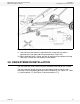
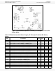
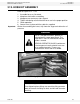
Figure 3.9 Self-Propelled Auger Frame Installation
9. One end of the crossbrace is attached to the v-frame tab, the other is
attached to the transport tube using clamp bands (Figure 3.9).
10. When attaching to the v-frame, be sure to mount one crossbrace to the top
side of the v-frame tab, and the other to the bottom.
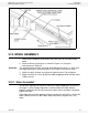
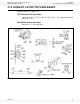
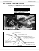
3.8. RAM EXTENSION INSTALLATION
The ram extension slides into the a-frame attached to the tabs on the v-frame.
The ram extension length must be set at the proper distance from the ram
mounting a-frame for proper operation of the transport kit (see Figure 3.8, Table
3.1 (measurement “C”) and Figure 3.10 (measurement “C”)).