Control/Communicator 5110XM Installation Instructions • Installation Instructions • Installation Instructions N8026 4/96
TABLE OF CONTENTS Section 1: GENERAL DESCRIPTION .............................................................................. 6 Basic Hardwired .............................................................................................................. 6 Remote Keypads ............................................................................................................ 6 User Codes ...................................................................................................................
Assigning Zone Descriptors ........................................................................................... 34 Entering Zone Descriptors ............................................................................................. 34 Programming the Descriptors ........................................................................................ 34 Alternate Method For Programming Zone Descriptors .................................................. 36 Adding Custom Words .......................
HOW TO USE THIS MANUAL This manual is written to accommodate both the new and the experienced installer of Ademco products. A general description of the entire system is located at the beginning of the manual. The wiring and physical setup of the hardware follows. The sections at the core of the manual include both hardware setup and programming requirements of each device to make that specific device operational in the system. A checkout procedure is included at the end of each section.
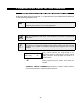
CONVENTIONS USED IN THIS MANUAL MAIN SECTION TITLES ARE SHOWN IN REVERSE TYPE Before you begin using this manual, it is important that you understand the meaning of the following symbols (icons). UL These notes include specific information which must be followed if you are installing this system for a UL Listed application. These notes include information that you should be aware of before continuing with the installation, and which, if not observed, could result in operational difficulties.
Section 1. GENERAL DESCRIPTION The Ademco 5110XM is a UL Listed, microprocessor-based fire alarm control/communicator that supports 5 style B (for further explanation of style B, refer to NFPA 72 National Fire Alarm Code Chapter 3: Protected Premises Fire Alarm Systems) hardwired zones. It may be used as a slave Digitial Alarm Communicator Transmitter (DACT) providing central or remote station service for a central or remote station listed Fire Alarm Control Panel (FACP).
Bell Output Provides one 12VDC (nominal), 1 AMP output, which may be configured for Style Y (for further explanation of style Y, refer to NFPA 72 National Fire Alarm Code Chapter 3: Protected Premises Fire Alarm Systems), EOLR supervision (for use with polarized alarm sounding devices) or for no supervision (no EOLR used) Auxiliary Relay Provides a built-in 12V wet or dry (jumper selectable) "Form C" relay which can be used for one of the following: • • • • Alarm activation on selected zones, silenced by C
Back-Up Battery Uses a rechargable 12VDC, 7AH/14AH maximum lead acid (gel cell) battery for back-up power (dual battery cable supplied) Agency Listings • UL864/NFPA 72 Central and Remote Station DACT and Local, central Station and Remote Station Control.
Section 2.
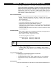
RETAINER CLIP (NOTE POSITION) LOCKED RETAINER CLIP RETAINER SLOTS UNLOCKED CABINET DOOR BOTTOM 1. Remove the cabinet door. It is easily removable for servicing and is easily re-installed. 2. Remove the lock knockout from the control cabinet door. Insert the key into the lock. Position the lock in the hole making certain that the latch will make contact with the latch bracket when the door is closed. 3. Hold the lock steady, and insert the retainer clip into the retainer slots.
1. Make sure that the mounting screws are tight. This insures that there is a good ground connection between the PC board and the cabinet. 2. Dress all wires away from microprocessor (the center section of the pc board). Use the tie-wrap loops on the left and right sidewalls of the cabinet for anchoring wires. This step is important for minimizing the risk of control radio frequency interference (RFI) with television reception.
The system will not switch to the backup dialer unless it detects a fault (less than 2 volts) on the main telephone line. This means that if a report does not go through on the main phone line due to a programming error, the backup dialer will not be activated. The 5110XM will transmit reports in the following order: alarms (fire, emergency), fire supervisories and troubles, then the remaining types of messages.
Section 3. INSTALLING REMOTE KEYPADS This section provides the following information: • A list of keypads that may be used • Instructions for wiring and mounting the keypads • A preliminary check-out procedure to ensure that the keypads are functioning properly in the system General When used as a slave DACT, a keypad is not required, but may be used to provide supplementary DACT status annunciation. The keypad may be mounted wherever needed.
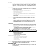
KEYPAD CONNECTOR CABLE (supplied with keypads) 20 19 18 YELLOW GREEN BLACK KEYPAD RED 17 Control Terminals Figure 3: Keypad Connections To The Control Board Mounting the Keypads 1. Make sure addressable type keypads (6137, 6137R, 6139, and 6139R) are set to the non-addressable mode (address 31), which is the factory default setting. Refer to the instructions provided with the keypad for address setting procedure. 2. Mount the keypads at a height that is convenient for the user.
Section 4. MECHANICS OF PROGRAMMING This section provides the following information: • How to enter and exit the programming mode • How to program a data field • How to review an entry in a data field • How to erase an entry in a data field • How to program user-friendly interactive modes (*56, *82) • Loading factory defaults General Programming Information Characteristics for each installation are stored in non-removable, electrically erasable, non-volatile EEROM memory.
desired data, then press programmed. [*] plus the next data field number to be 4. If you try to enter a non-existent field, the keypad will display EE or Entry Error. Simply re-enter [*] plus a valid field number. Reviewing a Data Field Press [#] plus Field No. Data will be displayed for that field number. No changes will be accepted in this mode. Erasing an Entry in a Data Field To delete an entry in a field, press [*] plus Field No. + [ *]. (Applies only to fields *40–*43, and *94).
Section 5. BASIC HARD-WIRED ZONES 1-5 This section provides the following information: • General information about hardwired zones • Installing 2-wire smoke detectors • Installing 4-wire smoke/combustion detectors • Programming hardwired zones • Checkout procedure for hardwired zones General Information about Hardwired Zones Provides 5 Style B supervised hardwired zones having the following characteristics: • EOLR supervision supporting N.O./N.C. contacts from a listed fire alarm control panel or N.O./N.C.
Remove 2000 ohm EOL resistor if connected across the zone terminals, and connect it across the loop wires at the last detector. 3. To supervise power, you MUST use a UL listed End-Of-Line Power Supervision Relay (i.e. System Sensor No. A77-716B).
@@@@@@@@e? @@@@@@@@e?@@@@@@@@?e@@@@@@@@e?@@@@@@@@?e@@@@@@@@e?@@@@@@@@?e@@@@@@@@e?@@@@@@@@?e@@@@@@@@e?@@@@@@@@?e@@@@@@@@ @@@@@@@@e? @@h?@@@@@@@@e?@@@@@@@@?e@@@@@@@@e?@@@@@@@@?e@@@@@@@@e?@@@@@@@@?e@@@@@@@@e?@@@@@@@@?e@@@@@@@@e?@@@@@@@@?e@@@@@@@@ @@ @@h? @@ @@h? @@ @@h? @@ @@h? @@ @@h? @@ @@ @@ @@ @@ @@ @@ @@ @@ @@ @@ @@ @@ @@ @@ @@ @@ @@ @@ @@ @@ @@ @@ @@ @@ @@ @@ @@ @@ @@ @@ @@ @@ @@ @@ @@ @@ @@ @@ @@ @@ @@ @@ @@ @@ @@ @@ @@ @@ @@ @@ @@ @@ @@ @@ @@ @@ @@ @@ @@ @@ @@ @@ @@ @@ @@ @@ @@ @@ @@ @@ @@ @@ @@ @
Programming Hard-Wired Zones 1. With at least one Alpha keypad (6139 or 6139R) connected to the keypad terminals on the control, power up the system temporarily. 2. Enter the programming mode by keying the following on the Alpha keypad: Master code (5 1 1 0) + 8 0. 3. Press *56 . Note that this is an interactive programming mode. You will use it to program zone numbers, zone types, and alarm report codes. Enter Zn Num.
02 Report Code 1st 03 2nd 12 The report code consists of 2 hexadecimal digits, each in turn consisting of 2 numerical digits. For example, for a report code of "3C", enter [0][3] for "3" and [1][2] for "C". Refer to Section 11. SYSTEM COMMUNICATION for complete information on report codes, if necessary. Enter the desired report code and then press [*] to continue. 3C Typical summary display Zn 02 ZT 09 Program Alpha? 0 = No 1 = Yes Enter Zn Num.
If the warning buzzer is sounding or if the following is displayed on an optional Alpha keypad, C h e c k xx Z on e xx press the silence/reset button (located on the upper right-hand side of the 5110XM pc board) to silence the warning buzzer. Restore any open zone(s) as necessary (also make sure that you have connected a 2000 ohm EOL resistor across the terminals of unused zones); Press the silence/reset button again to reset the system and clear the display.
Section 6. SYSTEM ZONES This section provides the following information: • General information about system zones • System zone assignments General Information System zones may be comprised of the following: • Zones which monitor various device connections, as well as earth ground faults • Keypad emergency zones, which may be assigned 24-hr.
Section 7. ALARM INDICATING DEVICES This section provides the following information: • General information about the bell circuit output • Connecting alarm indicating devices • Examples of compatible alarm indicating devices • Programming external sounder options General Information The 5110XM provides one bell circuit output rated 12VDC nominal (1014VDC), 1A max. which may be connected to 12V alarm indicating devices (horns, bells, sirens, etc.).
Sounder Connections Make connections to alarm output terminals 3 (+) and 4(-) (see Figure 6). To supervise the bell wiring, do the following: • Connect polarized 12V alarm indicating devices to the bell output terminals. • Attach a 2K EOLR (model #610-7, supplied) across the bell wires at the last device on wire run. • Program zone 6 for 24 hour trouble response (default setting). When supervision is not desired, do the following: • Cut the white jumper labeled W2 on control PC board.
7. Press *86 (Zones 10-12, 95, and 96 Bell / Aux. Relay Activation) 0 Enter [0] for NO ALARM ACTIVATION (* always enter [0] in the first space), [1] for BELL only, [2] for AUX. RELAY only, or [3] for BELL & AUX. RELAY. (default = [0] [0] [0] [0] [0] [0]) NOTE: Zones programmed for fire alarm response (zone types 09, 16, or 17) MUST be programmed to activate the bell output (can trigger the aux relay additionally). Therefore, option 1 or 3 must be selected for fire zones. 8.
Section 8: AUXILIARY RELAY CONNECTIONS This section provides the following information: • General information about the auxiliary relay • Wiring the auxiliary relay • Programming the auxiliary relay General Information The 5110XM provides on auxiliary relay output which may be configured as one of the following: • Wet 12VDC form C relay output • Dry, unsupervised form C relay output with contacts rated at 30VAC/VDC, 2A max.
Programming the Auxiliary Relay The auxiliary relay may be programmed for one of the following options: • Trouble/Supervisory Activation • Alarm Activation, silenced by [user code] + OFF • 4-Wire Smoke Detector Reset • Battery Saver • Alarm Activation, silenced by [user code] + # 67 These options are described below: • Trouble/Supervisory Activation (*34 = 0) : Steady activation in response to any zone or system related trouble condition or to any fire supervisory condition.
Section 9. FINAL POWER UP This section provides the following information: • • • • • Connecting the AC transformer Making earth ground connections Applying power to the control Installing the backup battery Backup battery calculations In Section 2, you made temporary power connections for the purpose of programming and testing the installation. This section provides information about final power-up procedures and battery size calculations.
2. Use a wire nut (not supplied) to splice this earth ground wire to the green flying lead located inside of and bonded to the transformer enclosure. Push the mated wires into the enclosure. 3. Connect the green flying lead which emerges from the top of the transformer enclosure to the 5110XM's earth ground terminal (Terminal 8). 4. Replace the transformer enclosure cover after wiring is complete. Powering Up the System Apply AC power to the control.
TOTAL STANDBY/ALARM LOAD WORKSHEETS To calculate the total current for the Aux. power, bell & aux. relay outputs, multiply each device's standby and/or alarm current by the number of units used. 1) Enter devices used on aux. power output, calculate standby and alarm currents, then add to get aux. power current subtotal. AUX. POWER OUTPUT Device Model # Device Current X # of Units Total Current Alarm = Standby Aux.
4) 5) Enter the calculated COMBINED AUX. POWER, BELL AND RELAY OUTPUT subtotals of all listed outputs then add to get Aux. Power Output Subtotal combined current. Bell Output Subtotal Aux. Relay Output Subtotal Add all subtotals (Cannot exceed 350mA max. standby; 1.0 amp max. alarm) Total Current Standby Alarm These values are fixed.
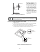
3. If two batteries are required, connect them in parallel using the dual battery harness. Both batteries should be mounted as shown in the figure below to ensure that neither battery's terminals can be shorted. Battery Fast-on tabs 12v battery Transformer Enclosure Note: When connecting batteries in parallel: - Use batteries from the same manufacturer and with the same voltage and capacity rating. - Use batteries with approximately the same age and state of charge.
Section 10. ALPHA DESCRIPTOR PROGRAMMING This section provides instructions for programming alpha descriptors, which is recommended for systems using alpha keypads. The ALPHA VOCABULARY LIST and CHARACTER CHART are found later in this section. Assigning Zone Descriptors The alpha keypad used with the 5110XM can have a user-friendly English language description/location of all protection zones and keypad emergency zones programmed into the system.
4. Press “0” (No).* The system will then automatically display the descriptor for zone 1. * The procedure for adding custom words to the built-in vocabulary will be found later under “Adding Custom Words”. Summary Mode Display Default Descriptor [ S ZN 0 1 ZO NE 0 1 Flashing Cursor (system is ready for entry of word). [ S ZN 0 1 A Flashing Cursor [ S ZN 0 1 B A CK S ZN 0 1 BA CK A + If a descriptor was not entered previously for zone 1, the default descriptor for zone 1 will be displayed.
S ZN 0 1 DO O R BA CK A + Flashing Cursor if “6” is pressed (system ready for next word). 9. Press “6” to accept the selected word. Note: If these are the only words you are using for the descriptor, press “ 8” instead of “6” to save them in memory. 10. The two words in our example have now been entered. Note, however, that up to three words may be entered (provided the number of characters will fit on the screen). Press “8” to save all words in memory.
4. For selection of the next word (e.g., DOOR), repeat step 3, as follows. Press key [3] until the first letter of the next word appears (e.g., "D"). Then press [6] to display the first available word beginning with that letter (e.g. DAUGHTERS). Press [3] repeatedly until the desired word (e.g., DOOR) appears. To accept the word, press [6], which toggles back to the alphabet list. 5. When all desired words have been entered, press [8] to store the description in memory. 6.
ALPHA VOCABULARY LIST (For Entering Zone Descriptors) 000 001 002 003 004 005 006 007 008 009 010 011 012 013 014 015 016 017 018 019 020 021 022 023 024 025 026 027 028 029 030 031 032 033 034 035 036 037 038 039 040 041 042 043 044 045 046 047 048 049 050 051 052 053 054 055 056 057 (Word Space) A AIR ALARM ALCOVE ALLEY AMBUSH ANTENNA AREA APARTMENT ART ATTIC AUDIO AUX AUXILIARY B BABY BACK BACKUP BAR BARN BASEMENT BATHROOM BED BEDROOM BELL BLOWER BOILER BOTTOM BOX BREAK BUILDING BURNER C CABINET CALL CA
CHARACTER (ASCII) CHART (For Adding Custom Words ) 32 (space) 33 ! 34 " 35 # 36 $ 37 % 38 & 39 ' 40 ( 41 ) 42 * 43 + 44 , 45 – 46 .
Section 11. SYSTEM COMMUNICATION This section provides the following information: • General information about system communication • An explanation of report formats • Programming communications options General Information The process of a successful transmission consists of both the method of communication between the control and the central station receiver and the actual way the information is sent and displayed at the central station.
The following describes each format in greater detail. 3+1 and 4+1 Standard Formats 3+1 and 4+1 Expanded Formats 4+2 Format Ademco Contact ID Reporting Format Comprise a 3- (or 4-) digit subscriber number and a single digit report code (e.g. Alarm, Trouble, Restore, etc.). Comprise a 3- (or 4-) digit subscriber number, and a two-digit report code. The first digit is displayed on the first line, followed by a second line where the first digit is repeated 3 (or 4) times and followed by the second digit.
Where: SSS or SSSS = A= Z= Subscriber ID Alarm Code–1st digit Typically Zone Number*–2nd digit Trouble Code (1st & 2nd digits) Gg = GOGO2 = WS W S2 = SPSP2 = Bb = EAC = Supervisory Code (1st & 2nd digits) W EWE2 = LL B = RBb = Low Battery Code(1st & 2nd digits) Tt = Bypass Code (1st & 2nd digits) AC Loss Code (1st & 2nd digits) Walk Test End (1st & 2nd digits) Walk Test Start (1st & 2nd digits) R= RSRS2 = R Tt = Test Code (1st & 2nd digits) Off Nornal Test Code (1st & 2nd digits) Restore Code
Programming Communication Options To program communications options, do the following: 1. With at least one alpha keypad (6139 or 6139R) connected to the system, power up the system. If necessary, refer to the Final PowerUp section for the power-up procedure. 2. Enter the programming mode by keying the following on the alpha keypad: Master code (5 1 1 0) + 8 0 Press *33 BACKUP DIALER PULSE/TONE Enter 0 for pulse dial, 1 for tone dial.
Press *47 SPLIT/DUAL REPORTING Enter 0 to disable (Backup report only). This is the default. 1= 2= 3= 4= 5= TO PRIMARY Alarms, Restore All except Test Alarms, Restore All except Test All TO SECONDARY Others Test All All All Press * 49 PERIODIC TEST REPORT Select the desired test report interval. 0 = none; 1 = 24 hours (default) ; 2 = weekly; 3 = 30 days. Test Report Code entered in field * 64 or * 84 is sent. Must be set to "1" for fire installations.
This will be sent when the supervisory condition is restored. Press *60 TROUBLE REPORT CODE This will be sent if a zone goes into trouble. | Press *61 BYPASS REPORT CODE This will be sent when a zone is manually bypassed. | Press *62 AC LOSS REPORT CODE | Timing of this report is random within 6-12 hours after AC is lost. If AC restores before the report goes out, there is no AC loss report.
Press *95 RING DETECTION COUNT FOR DOWNLOADING Refer to the chart below and program this field accordingly. Answering Machine Downloading *96 Field * 95 Programming No No Set for value of “0” Yes No Set for value of “0” No Yes Set for value other than “0” (1–14). Yes Yes “15” to bypass answering machine. INITIALIZE DOWNLOAD ID AND SUBSCRIBER ACCT. No. FOR DOWNLOADING (No data entry required) This completes the communication programming. Exit the programming mode by keying *99.
Section 12. ZONE RESPONSE TYPE DEFINITIONS This section provides the following information: • General information about zone response types • Zone response types General Information You must assign a zone type to each zone, which will define the way in which the system will respond to faults in that zone. Zone types are defined below. Zone Response Types Type 00 Zone Not Used Type 06 24-hour Silent Alarm • Program this zone type for zones that are not used.
Type 17 Fire Waterflow Alarm • Provides a fire alarm when zone is shorted for longer than the time programmed in field *78 delay time setting. The combined sensor and program field *78 delay must not exceed 90 seconds. • Provides either a trouble on an open circuit (field *32=0) or a supervisory on open circuit (field *32=1). • Usually assigned to a zone containing a fire sprinkler waterflow sensor. • Bell output may be programmed to remain latched on alarm or to restore when zone restores (see field *76).
Section 13. DATA FIELD DESCRIPTIONS Description of System Data Fields THE BLANK PROGRAMMING FORM INCLUDED WITH THIS MANUAL SHOULD BE USED TO RECORD THE DATA FOR THIS INSTALLATION Defaults (where applicable) Are Indicated In Text The following is a table containing a list of all data fields in this control (presented in numerical order).
DIALER PROGRAMMING (*40–*50) Fields * 40, * 41, *42: Enter up to the number of digits shown. Do not fill unused spaces. Enter 0–9, # + 11 for " *" # + 12 for "#’" # + 13 for a pause (2.5 secs) *31 AUXILIARY RELAY TIMEOUT This field determines whether the auxiliary relay will shut off after time allotted, or continue until manually turned off. Enter as follows: 0 = No timeout; 1 = 4 min.; 2 = 8 min.; 3 = 12 min.; 4 = 16 min.
*46 REPORT FORMAT (* applies to BOTH primary and secondary numbers) Determines which format is to be used to report to the central station. 0 = 3+1; 4+1 ADEMCO Low Speed Standard (this is the default) 1 = 3+1; 4+1 Radionics Standard 2 = 4+2 ADEMCO Low Speed Standard 3 = 4+2 Radionics Standard 6 = 4+2 ADEMCO Express 7 = ADEMCO Contact ID Reporting (* Recommended) 8 = 3+1; 4+1 ADEMCO Low Speed Expanded 9 = 3+1; 4+1 Radionics Expanded *47 SPLIT/DUAL REPORTING Enter 0 to disable (Backup report only).
↓ Zone Number 01 Zone Type Fire 09 Zone Type ↑ Zone Type (ZT): Each zone must be assigned to a zone type, which defines the way in which the system responds to faults in that zone. Enter the zone type code (or change it, if necessary). Zone types are listed below. 00 = Not Used 06 = 24 Hr Silent 07 = 24 Hr Audible 08 = 24 Hr Aux 09 = Fire W/verification. 16 = Fire w/ Verification 17 = Fire Waterflow 18 = Fire Supervisory 19 = 24 Hour Trouble Default values for zones 01 to 05 are: Zone No.
01 Zone Type Not Used 3. To either temporarily or permanently remove a zone from the system, go into programming mode and press [*][5][6]. Enter the zone number and press [*]. At the “Zone Type” prompt, enter [0][0] and [*]. This sets the type of the zone to “Not Used”. The next prompt will be "Delete Zone?". "Yes" will permanently remove the zone from the system, while "No" will disable it but retain all data except the original zone type.
RESTORE REPORT CODES (*69–*74) *64 NORMAL TEST REPORT CODE | This is sent periodically to test that the communicator and phone lines are operational (frequency of report is selected in field *49). *69 GROUP RESTORES FOR TROUBLE, BYPASS Enter 0 for no (report for each restore), or 1 for yes (report after all zones restored). Default is “0”. Note: "1" not applicable to Contact ID reporting. *70 ALARM RESTORE REPORT CODE, 1st DIGIT This is sent when a zone alarm has been restored.
*85 ZONES 1-7 BELL & AUX. RELAY ACTIVATION 1 2 3 4 5 6 7 0 = none (default for 6 and 7); 1 = bell only (default for 1-5) 2 = aux. relay only; 3 = bell & aux. relay DOWNLOAD INFORMATION (*94, *95) *86 ZONES 10-12, 95 and 96 BELL & AUX. RELAY ACTIVATION 0 10 11 12 95 96 0 = none (default) ; 1 = bell only; 2 = aux. relay only; 3 = bell & aux. relay *94 DOWNLOAD PHONE NUMBER Enter up to 12 digits; | | | | | | | | | | | 0–9, # +11 for “*”, # + 12 for “#”, # + 13 for a pause. Do not fill unused spaces.
Section 14. REMOTE PROGRAMMING AND CONTROL (DOWNLOADING) General Information UL The Ademco 5110XM can be remotely programmed from an IBM compatible Personal Computer (PC), a HAYES Modem, and Ademco's V-LINK® Software (as specified below). Programming the control from a remote location is protected against compromise by someone attempting to defeat the system, using multi-levels of security protection: 1.
Central Station Initiated: 1. Enter program mode by entering Master code (5110) + 8 0. 2. Program the download phone number in field *94. 3. Program the ring detect count to "4" in field *95. The central station can change this as required when on-line with the control. 4. Initialize the download ID and subscriber account number by entering *96. 5. Exit program mode by entering *98 (prevents re-entry using Master code) or *99 (allows re-entry using Master code). 6. Wait approx.
Section 15. SYSTEM OPERATION This section provides the following information: • User codes • Keypad functions • Emergency keys User Codes * User codes are required only if a keypad is installed on the control. This system provides 1 Master code and 5 secondary codes (Users 2-6). These are described below. Master Code The installer programs the 4-digit Master Code initially as part of the programming procedure. The factory default Master code is "5-1-1-0 ", but may be changed in field *20.
Keypad Functions The keypad, if used, allows the user to silence alarm and trouble sounders and perform other system functions, such as bypassing zones, and display zone descriptors. Zone and system conditions (alarm, trouble, bypass) are displayed in the Display Window. The system is in the "System Normal" condition when all zones are intact. If NOT, faulted zones will be displayed in numerical order. System Commands The following is a brief list of system commands.
Section 16. TESTING THE SYSTEM Test Procedure After installation is completed, the 5110XM System should be carefully tested, as follows: 1. With the System in the "SYSTEM NORMAL" state all zones should be intact. If a fault message is displayed, press the [*] key to display the faulted zone(s). Restore faulted zone(s) if necessary, so that "SYSTEM NORMAL" message is displayed. 2.
Dialer Test The 5110XM may be programmed to send periodic test reports ranging from every 24 hours, weekly, or monthly, as determined in field *49. The first test report will be sent 12 hours after initial powerup, after exiting the program mode, or after a download session, whichever is applicable. As long as there are no existing alarm, supervisory, or trouble conditions present the normal test report will be sent (as programmed in field *64).
Section 17. TROUBLESHOOTING GUIDE SYST EM SYMPTOM POSSIBLE CAUSE REMEDY 1. Low Battery message on keypad or battery trouble LED lit. 1a. "Bat" or “System Low Bat” 1a. System battery is low or missing. 2. Nuisance or phantom alarm. 2a. Sensors not properly installed, wired, or monitored. 2a. Check installation to see if in accor dance with established procedure. 3. "AC POWER" light off. 3a. Interrupted AC power supply. 3a. Check transformer connection and Power line cir cuit breaker. 4.
CONTACTING TECHNICAL SUPPORT PLEASE, Before you call Technical Support, be sure you: • READ THE INSTRUCTIONS! • Be on site with all documentation (manual, prigram form, etc.) • Check all wiring connections. • Determine that the power supply and/or backup battery are supplying proper voltages. • Verify your programming information where applicable. • Note the proper model number of this product, and the version level (if known) along with any documentation that came with the product.
Section 18. SPECIFICATIONS & ACCESSORIES Specifications –––––––––––––––––––––––––––––––––––––––––––––––––––– CONTROL 1. Physical: 12-1/2" W x 14-1/2" H x 3" D (318mm x 368mm x 76mm) 2. Electrical: VOLTAGE INPUT: from built-in transformer supplying 18VAC at 40VA to 5110XM. Transformer requires nominal 120VAC, 600mA input. RECHARGEABLE BACK-UP BATTERY: 12VDC, 7AH min., 14AH, max. (Gel type). Charging Voltage: 13.7VDC, nominal BELL OUTPUT: 12VDC, 1.0A output.
AGENCY LISTINGS Fire: • UL864-NFPA 72 Central Station and Remote Station DACT and local, central station and remote station control.
Accessories (Compatible Devices) ––––––––––––––––––––––––––––––––––– Sounders System Sensor PA400B (beige)/PA400R (red) System Sensor MA-12/24 System Sensor SS1215 ADA System Sensor SS121575 ADA System Sensor SS-12 System Sensor MA/SS-12 System Sensor MASS1215 ADA System Sensor MASS121575 ADA Wheelock LS1-12-VFR Wheelock MS1-12-VFR Wheelock MT-12-LS-VFR Wheelock MT4-12-LS-VFR Wheelock MT-12-MS-VFR Wheelock MT4-12-MS-VFR Gentex GXS-2-15 Gentex GXS-2-1575 Gentex SHG-12-15 Gentex SHG-12-1575 Faraday 5336L-U-14
REGULATORY AGENCY STATEMENTS The 5110XM may be used as a slave DACT providing central or remote station service for a central or remote station listed local FACP. The 5110XM may also be used as a stand-alone local, central station or remote station control. Some comments that apply to these installations are listed below: When used as a slave DACT: * Wire the 5110XM's hard-wired zones to the FACP alarm, supervisory and trouble contacts. Each zone must have a 2k EOLR installed at the FACP.
FEDERAL COMMUNICATIONS COMMISSION (FCC) Part 68 STATEMENT This equipment complies with Part 68 of the FCC rules. On the front cover of this equipment is a label that contains, among other information, the FCC registration number and ringer equivalence number (REN) for this equipment. If requested, this information must be provided to the telephone company. This equipment uses the following jacks: An RJ31X is used to connect this equipment to the telephone network.
WARNING THE LIMITATIONS OF THIS ALARM SYSTEM While this System is an advanced design security system, it does not offer guaranteed protection against burglary, fire or other emergency. Any alarm system, whether commercial or residential, is subject to compromise or failure to warn for a vari ety of reasons. For example: • Intrusion detectors (e.g., passive infrared detectors), smoke detectors, and many other sensing devices will not work without power.
ADEMCO LIMITED WARRANTY Alarm Device Manufacturing Company, a Division of Pittway Corporation, and its divisions, subsidiaries and affiliates ("Seller"), 165 Eileen Way, Syosset, New York 11791, warrants its products to be in conformance with its own plans and specifications and to be free from defects in materials and workmanship under normal use and service for 24 months from the date stamp control on the product or, for products not having an Ademco date stamp, for 12 months from date of original purchas
INDEX Auxiliary Relay, 7 AUXILIARY RELAY CONNECTIONS, 27 Auxiliary Relay Disable, 23 AUXILIARY RELAY TIMEOUT, 50 -BBack-Up Battery, 8,12 Back-up Dialer Supervision, 23 Backup Dialer, 6 Basic Hardwired, 6 BASIC HARD-WIRED ZONES 1-5, 17 "BAT", 61 battery connector, 33 Battery Saver Option, 28 Battery Supervision, 33 Bell Output, 6 Bell Supervision, 23 bells, 24 Built-in Indicators and Switches, 7 Busy-Standby, 30, 61 BYPASS REPORT CODE, 45, 53 BYPASS RESTORE REPORT CODE, 45, 54 Bypassing Zones, 59 1100, 19,.
Default Descriptor , 35 DEFAULT VALUES, 55 Description of System Data Fields, 49 Dialer Operation, 11 DIALER PROGRAMMING, 50 Dialer Test, 61 DOWNLOAD INFORMATION, 55 DOWNLOAD PHONE NUMBER , 45,55 Downloading, 46, 55 kissoff, 40 -EEarth Ground, 12, 29 Earth Ground Supervision, 23 EEROM, 7 Emergency Keys, 59 Entering Program Mode, 15 Entering Zone Descriptors, 34 EOLR, 6, 14, 18, 22 Erasing an Entry in a Data Field, 16 Exiting the Programming Mode, 16, 55 Expanded or 4+2 Format, 44, 53 external sounder opti
SESCOA/RADIONICS SELECT, 44, 51 Silence/Reset key, 19, 22 Silencing Sounders, 59 sirens, 24 Site Initiated Remote Programming, 56 slave DACT, 6 SMARTMODEM 1200, 56 smoke detectors, 6 Sounder Connections , 25 Sounders, 66 SPECIFICATIONS & ACCESSORIES, 64 SPLIT/DUAL REPORTING, 44, 51 Station Initiated Remote Programming, 56 SUBSCRIBER ACCOUNT. No.
NOTES –74–
5110XM SUMMARY OF CONNECTIONS WARNING: OWNER’S INSTRUCTION NOTICE NOT TO BE REMOVED Refer to the 5110XM Installation Instructions N8026 for additional information MAY BE USED AS A SLAVE DACT PROVIDING CENTRAL OR REMOTE STATION SERVICE FOR A CENTRAL OR REMOTE STATION UL LISTED FACP. MAY ALSO BE USED AS A STAND-ALONE NON-CODED LOCAL, CENTRAL STATION AND REMOTE STATION PROTECTED PREMISES UNIT PROVIDING MANUAL FIRE ALARM, AUTOMATIC FIRE ALARM, SPRINKLER SUPERVISORY AND WATER FLOW ALARM.
A LA RM DE V IC E M A NUFA C TURING C O.