
Instruction manual

P84030 D
Sheet 1 of 10
273 Branchport Avenue
Long Branch, NJ 07740
(800) 631-2148 Thank you for using our products.
www.wheelockinc.com
INSTALLATION INSTRUCTIONS
SERIES NS TWO WIRE APPLIANCES
(WALL MOUNT VERSIONS)
Use this product according to this instruction manual. Please keep this instruction manual for future reference.
GENERAL:
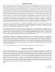
Wheelock’s Series NS Horn Strobe Appliances require only 2-wires for operation of the horn and strobe appliance and provide a
selectable continuous or Code 3 Horn tone and continuous strobe when connected directly to the Fire Alarm Control Panel (FACP).
They can also provide a synchronized Code 3 horn tone and synchronized strobe when used in conjunction with a Sync Module (SM),
Dual Sync Module (DSM) or Power Supply (PS-12/24-8). They are the ideal choice for applications where the audible silence feature
is required. The NS Appliances are UL Listed under Standard 1971 for Signaling Devices for the Hearing Impaired and UL Standard
464 for Audible Signal Appliances. They are listed for indoor use only
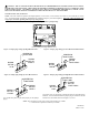
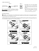
and equipped with a NS Mounting Plate (NSMP) that can be
mounted to single-gang, double-gang, 4” backbox, 100mm European backbox or SHBB surface backbox (See Mounting Options).
These strobe models are Listed for wall mounting only
. The NS Appliances use a Xenon flashtube with solid state circuitry enclosed
in a rugged Lexan lens to provide maximum visibility and reliability for effective visible signaling.
Series NS Appliances can be field set for High (HI) or Low (LO) dBA sound output.
These strobe models are designed for use with either filtered DC (VDC) or unfiltered Full-Wave-Rectified (FWR) input voltage. All
inputs are polarized for compatibility with standard reverse polarity supervision of circuit wiring by a FACP.
NOTE: All CAUTIONS and WARNINGS are identified by the symbol
. All warnings are printed in bold capital letters
WARNING: PLEASE READ THESE INSTRUCTIONS CAREFULLY BEFORE USING THIS PRODUCT. FAILURE
TO COMPLY WITH ANY OF THE FOLLOWING INSTRUCTIONS, CAUTIONS AND WARNINGS COULD RESULT IN
IMPROPER APPLICATION, INSTALLATION AND/OR OPERATION OF THESE PRODUCTS IN AN EMERGENCY
SITUATION, WHICH COULD RESULT IN PROPERTY DAMAGE AND SERIOUS INJURY OR DEATH TO YOU
AND/OR OTHERS.
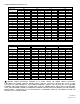
SPECIFICATIONS:
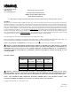
Table 1: UL Ratings
Models
Regulated
Voltage
(VDC/VRMS)
Voltage
Range
(VDC/VRMS)
Strobe
Candela
(cd)
NS-2415W 24 16.0-33.0 15
NS-2430W 24 16.0-33.0 30
NS-2475W 24 16.0-33.0 75
NS-24110W 24 16.0-33.0 110
NS-1215W 12 8.0-17.5 15
WARNING: THESE APPLIANCES WERE TESTED TO THE OPERATING VOLTAGE LIMITS OF 16-33 VOLTS
FOR 24V MODELS AND 8-17.5 VOLTS FOR 12V MODELS USING FILTERED (DC) OR UNFILTERED FULL-WAVE-
RECTIFIED (FWR). DO NOT APPLY 80% AND 110% OF THESE VOLTAGE VALUES FOR SYSTEM OPERATION.
NOTE: THE MAXIMUM WIRE IMPEDENCE BETWEEN STROBES SHALL NOT EXCEED 35 OHMS. THE
MAXIMUM NUMBER OF STROBES ON A SINGLE NAC CIRCUIT SHALL NOT EXCEED 47.
Copyright 2001 Wheelock, Inc. All rights reserved.