FireForce 8 NOTIFICATION APPLIANCE CIRCUIT EXPANDER INSTALLATION & OPERATION MANUAL P/N 52257:B • ECN 06-683 • 09/27/2006
Fire Alarm System Limitations While a fire alarm system may lower insurance rates, it is not a substitute for fire insurance! An automatic fire alarm system—typically made up of smoke detectors, heat detectors, manual pull stations, audible warning devices, and a fire alarm control panel with remote notification capability—can provide early warning of a developing fire. Such a system, however, does not assure protection against property damage or loss of life resulting from a fire.
Installation Precautions Adherence to the following will aid in problem-free installation with long-term reliability: WARNING - Several different sources of power can be connected to the fire alarm control panel. Disconnect all sources of power before servicing. Control unit and associated equipment may be damaged by removing and/or inserting cards, modules, or interconnecting cables while the unit is energized. Do not attempt to install, service, or operate this unit until manuals are read and understood.
Documentation Feedback Your feedback helps us keep our documentation up-to-date and accurate. If you have any comments or suggestions about our online Help or printed manuals, you can email us.
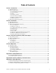
Table of Contents Section 1 Introduction ............................................................................................................ 7 1.1: General Description .......................................................................................................................................7 1.2: Functional Description...................................................................................................................................7 1.2.1: Normal Quiescent Operation ....
Table of Contents 6 FireForce 8 Installation & Operation Manual P/N 52257:B 09/27/2006
Section 1: Introduction 1.1 General Description The FIREFORCE 8 is a notification appliance circuit extender panel designed to extend the power capabilities of the existing notification appliance circuits and provide power for other ancillary devices. An FIREFORCE 8 panel consists of two notification appliance circuit inputs and four class B, style Y, two class A, style Z, or two class B and one class A notification appliance circuits.
Introduction Functional Description 1.2.3 Reset The FIREFORCE 8 will return to the quiescent condition automatically upon restoration of the Main FACP to normal operation 1.2.4 Trouble Condition A trouble condition is indicated by a TRBL LED illuminating and the common Form “C” TROUBLE FAIL relay contacts transferring. The trouble signal will be transmitted to the Main FACPs by opening the Indicating Circuits that are used to control the FIREFORCE 8.
Electrical Operating Characteristics Introduction 1.3 Electrical Operating Characteristics Input Voltage 120 VAC @ 3.3 Amps or 240 VAC @ 2 Amps (Jumper selected)50/60 Hz. Input Control Signal 10VDC to 30VDC, or 12V to 28V Full Wave Rectified, Polarity Reversing. Output Voltage 24 Volt DC @ 8Amps NAC outputs 1- 4 3.0 Amps Maximum per output. NAC outputs 1- 4 With optional Class A adapter 2.5 Amps Maximum per output. AUX Power 0.15 Amps under all conditions. 2.
Introduction 10 Electrical Operating Characteristics FireForce 8 Installation & Operation Manual P/N 52257:B 09/27/2006
Section 2: Installation 2.1 Mounting Instructions The standard mounting is a surface mount cabinet. The unit must be securely attached to a permanent partition using suitable fasteners. Four mounting holes are provided to accept 1/4-inch dia. screws max. There are nine combination knockouts provided, located three on the top and three on each side of the cabinet. Knockouts can accept 1/2, or 3/4 inch conduit. 2.2 Electrical Connections For field wiring connections, refer to Inter-equipment Wiring DWG. No.
Installation Function of Input/Output Connections 2.3.4 Earth Ground Connect to Earth Ground on the Power Supply module. Earth Ground Connections J1 Terminals GND 2.3.5 Trouble Relay The common trouble relay is a normally energized Form C relay that transfers when the FIREFORCE 8 detects a trouble condition. The contacts are rated for 2 amps @ 30VDC with a power factor of 0.6 or higher. Trouble Fail TB2 Terminals NC Comm NO 2.3.
Function of Input/Output Connections Installation 2.3.8 Reference EOL Resistor (Power Limited) To accommodate existing Notification Appliance circuits that have EOL resistors of various values, provisions are made to attach a reference EOL resistor, matching the existing EOL, within the range of 2.0K to 25.0K ohms. Normally, a 3.9K resistor should be attached to the Ref. Terminals. All Style Y (Class B) outputs must have EOL resistors of the same value as the reference resistor.
Installation 14 Function of Input/Output Connections FireForce 8 Installation & Operation Manual P/N 52257:B 09/27/2006
Section 3: Function of Switches, LEDs and Jumpers 3.1 Programming Switches Outputs 1 & 2 SW-1.1 SW-1.2 Function SIG1/2A SIG1/2B Open Open Output follows the Input (Also passes Sync. signals) Should NOT be used for Full Wave Rectified inputs Closed Open Steady Input, Temporal Output Open Closed Steady Input, Steady Output, Strobe Sync. added Closed Closed Steady input, steady output, noise eliminated. (Does NOT pass Sync. signals) Outputs 3 & 4 SW-1.3 SW-1.
Function of Switches, LEDs and Jumpers Function of LED Indicators 3.2 Function of LED Indicators INDICATOR LED# Color Description PWR ON LED # 8 Green Indicates AC line operation. AUX TRBL LED # 7 Yellow Indicates a short or overload on the Aux. Output. BATT TRBL LED # 6 Yellow Indicates a low battery voltage or missing battery. GF TRBL LED # 5 Yellow Indicates an external wiring connection is not adequately isolated from the earth ground.
Section 4: Operation 4.1 Start-up Procedure Connect A.C. first, then connect batteries 4.2 Operating Instructions 4.2.1 Alarm Condition Alarm devices operate in unison with the Main FACP alarm devices. The alarm-activated outputs are reset through operation of the Reset switch on the Main FACP. 4.2.2 Trouble Condition The associated trouble LED (yellow) will illuminate. 4.2.3 Testing and Maintenance System Testing should be performed periodically to insure proper operation. 1.
Operation 18 Battery Applications FireForce 8 Installation & Operation Manual P/N 52257:B 09/27/2006
Appendix A: Compatible Devices A.
Compatible Devices Synchronized Horns and Strobes A.
Appendix B: FireForce 8 Battery Calculation Chart Circuit Normal Current Notification Appliance Ckt. 1 Alarm Current Cl A, .050A + Device Load 1 or Cl B, .065A + Device Load 1 & 2 Or Class A Adapter, .065A + Device Load 1 & 2 Notification Appliance Ckt. 2 Notification Appliance Ckt. 3 Cl A, .050A + Device Load 3 or Cl B, .065A + Device Load 3 & 4 Or Class A Adapter, .065A + Device Load 3 & 4 Notification Appliance Ckt. 4 External Load A+, A+/- 24 VDC Common Control .
FireForce 8 Battery Calculation Chart 22 FireForce 8 Installation & Operation Manual P/N 52257:B 09/27/2006
Appendix C: Wiring Drawings C.1 B-W479 Wiring Diagram: Notification Circuit Expander N/C COMM N/O POWER FAIL L1 GND L2 B-W479rotatedgw.
Wiring Drawings B-W479-1 Wiring Diagram: Synchronized Horn & Strobe N/C COMM N/O TROUBLE FAIL 24 N/C COMM N/O POWER FAIL N/C COMM N/O TROUBLE FAIL N/C COMM N/O POWER FAIL B-W479-1rotatedgw.ai C.
C-M822, Assembly Drawing, FireForce 8 Cabinet Wiring Drawings C.
Wiring Drawings 26 C-M822, Assembly Drawing, FireForce 8 Cabinet FireForce 8 Installation & Operation Manual P/N 52257:B 09/27/2006
FireForce 8 Installation & Operation Manual P/N 52257:B 09/27/2006 27
Automation and Control Solutions Honeywell Power Products l2 Clintonville Road Northford, CT 06472 www.honeywellpower.com ® U.S. Registered Trademark © 2005 Honeywell International Inc. 52257 HonRev. Rev.