
Instruction manual


P83601 F
Sheet 7 of 11
WIRING INFORMATION:
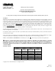
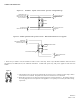
Figure 6: Audible signal and strobe operate independently.
FROM FIRE ALARM
CONTROL PANEL (FACP).
PRECEDING APPLIANCE
OR SYNC MODULE *
FROM FACP OR
PRECEDING APPLIANCE
TO NEXT APPLIANCE
OR EOLR
TO NEXT APPLIANCE
OR END-OF-LINE
RESISTOR (EOLR).
STROBE
AUDIBLE
Figure 6A: Audible signal and strobe operate in unison . Red and black shunt wires are supplied.
+
-
-
+
+
-
-
+
FROM FACP
PRECEDING APPLIANCE
OR SYNC MODULE *
BLACK SHUNT WIRE
RED SHUNT WIRE
TO NEXT APPLIANCE
OR EOLR
STROBE
AUDIBLE
* When the sync module is used, the audible tone will be Code 3 sound only. Refer to Sync Module Installation Instruction sheets
SM (P83123) and DSM (P83177) for additional information. Audible will operate only with power applied to both strobe and
audible.
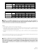
Figure 7.
1) NS4 Appliances have in-out wiring terminals that accepts two #12 to 18 American Wire Gauge (AWG)
wires at each screw terminal. Strip leads 3/8” inches for connection to screw terminals.
2) Break all in-out wire runs on supervised circuit supervision as shown in Figure 7. The polarity shown in
the wiring diagrams is for the operation of the appliances. The polarity is reversed by the FACP during
supervision.