SAFEPATH4 AUDIO BOOSTER SPB-80/4 P/N 108988 SPB-160 P/N 108989 SPB-160/B P/N 109930 SPB-80/4-B P/N 109931 Installation, Testing, Operation, and Maintenance Manual 273 Branchport Avenue, Long Branch, NJ 07740-6899 Ph: (800) 631-2148 Fax: (732) 222-2588 Toll Free 800-631-2148 Web Site: www.cooperwheelockinc.com E-Mail: info@wheelockinc.
Intentionally Blank 2
Typographical Notation Conventions Thank you for using our products. Use this product according to this instruction manual. Please keep this instruction manual for future reference.
Intentionally Blank 4
Table of Contents Typographical Notation Conventions………………………………………………………..…… 3 Table of Contents……………………………………………………………………………..……. 5 List of Figures………………………………………………………………………………..……… 7 List of Tables………………………………………………………………………………..………. 8 Chapter 1 – Safety Precautions……………………………………………………………..……. 9 Section 1-1 – Read This Manual…………………………………………………..………. 9 Section 1-2 – Operational Safety……………………………………………………..
Chapter 6 – Periodic Testing and Maintenance………………………………………………. 46 Section 6-1 – Introduction………………………………………………………………… 46 Section 6-2 – Periodic Testing……………………………………………………………...46 Section 6-3 – Faulty Equipment…………………………………………………………….46 Section 6-4 – Qualified Personnel………………………………………………………….46 Section 6-5 – Miscellaneous Hardware Testing…………………………………………. 47 Chapter 7 – Troubleshooting……………………………………………………………………….48 Section 7-1 – Introduction………………………………………………….……………….
List of Figures Figure 2-1 Basic Capabilities of the SPB-80/4 SAFEPATH4 Audio Booster Panel……….… 15 Figure 2-2 Basic Capabilities of the SPB-160/4 SAFEPATH4 Audio Booster Panel…….…. 15 Figure 2-3 Layout of a SPB-80/4 SAFEPATH4 Audio Booster Panel………....…………....... 16 Figure 2-4 Layout of a SPB-160 SAFEPATH Audio Booster Panel………………………..…. 17 Figure 3-1 Connections for Multiple Audio Booster in Two-Wire Mode (SPB-160)………..…..
List of Tables Table 2-1 Standard Features……………………………………………………………………. 14 Table 3-1 Terminal Connection Definitions……………….…………….……………………… 25 Table 3-2 Jumper/Switch/Variable Resistor Functions…………………………………………37 Table 6-1 Miscellaneous Hardware Tests………………………………………..……………. 47 Table 7-1 Trouble LED Procedure Cross Reference……………………………………..…… 51 Table 8-1 Mechanical………………………………………………………………………………57 Table 8-2 Environmental…………………………………………………………………………..
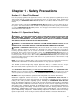
Chapter 1 - Safety Precautions Section 1-1 - Read This Manual Personnel properly qualified in the application and use of life safety equipment ("qualified personnel") shall read this manual carefully before performing any actions to specify, apply, install, maintain and operationally test SAFEPATH4 Audio Booster products in accordance with the instructions in this manual. This manual shall be kept with the SAFEPATH4 Audio Booster panel for reference during the life of the system.
WARNING: FOR PROPER OPERATION IN LIFE SAFETY APPLICATIONS, THE SAFEPATH4 AUDIO BOOSTER PANEL SHALL BE CONNECTED TO A LISTED COMPATIBLE AND PROPERLY OPERATING VOICE EVACUATION PANEL SUCH AS THE WHEELOCK SP40/2 PANEL, WHICH CONTROLS ITS ACTIVATION. ALL EQUIPMENT SHALL BE PROPERLY INTERCONNECTED AND OPERATING.
CAUTION: The output of the audio system may not be heard in all cases. Sound can be blocked or reduced by walls, doors, carpeting, wall coverings, furniture, insulation, bed coverings, and other obstacles that may temporarily or permanently impede the output of the audio system. Sound is also reduced by distance and masked by background noise.
Intentionally Blank 12
Chapter 2 - Overview and Features Section 2-1- Description General The SAFEPATH4 AUDIO BOOSTER panel provides additional or remote amplification for Wheelock Voice Evacuation panels. It is designed to boost the capacity of the SP40/2 panel by increasing the output wattage of the 25V or 70.7V audio output. There are two models of the audio booster. Model SPB-80/4 contains an 80 Watt, 25V or 70.7V, supervised audio output with two supervised and synchronized selectable 2 Amp strobe outputs.
Standard Features Table 2-1 Standard Features Feature Strobe Input Circuit Strobe Output Circuit SPB-80/4 Power limited 8-33VDC NAC or CC strobe Activation SPB-160 No Strobe Circuits. Two - 24VDC, 2A Max NAC Supervised power limited strobe outputs. Selectable Outputs: Wheelock Sync, Wheelock Pass Through, or Constant DC. Trouble LED's for open and short output conditions Supervised with 10K Ohm EOLR. Audio Input Circuit One 1.2 Watt 25V or 70.7V input One 1.2 Watt 25V or 70.
Audio Out 25V or 70V at 80 Watts, Supervised Audio In 25V or 70.7V Strobe In 8-33VDC or Contact Closure Strobe 1 Out 24VDC at 2A, Supervised Strobe 2 Out 24VDC at 2A, Supervised SPB-80/4 Expansion Out 24VDC at 0.5A in Alarm Condition Supervised DC OUT Constant 24VDC at 0.5A Unsupervised for Splitter Power Auxiliary In. For Alarm Operation of Amplifier when operating on Battery Only.
GND N L PS _ PS+ P82798 REV.
24VDC POWER SUPPLY GND N L PS _ PS+ P82798 REV.
Intentionally Blank 18
Chapter 3 - Installation and Setup Section 3-1 - Introduction The lives of people depend upon your safe and proper installation of the voice evacuation system and the Audio Booster Panel. Please read, understand and carefully follow the specific installation instructions set forth below to avoid damage to the panel and equipment connected to it. Only qualified personnel in accordance with the procedures in this manual should conduct installation.
SP40/2 AUD OUT AUDIO BOOSTER W1 Closed W10 Closed AUD IN AUD RET AUDIO BOOSTER W1 Closed W10 Closed AUD IN AUD RET AUDIO BOOSTER UL Listed 10K Ohm EOLR W1 Closed W10 Closed AUD IN AUD RET Figure 3-1 Connections for Multiple Audio Booster in Two-Wire Mode The Four Wire Audio Mode is used when multiple Audio Boosters are used on the output of the SP40/2 and it is not desirable to lose secondary operations when a single audio booster goes into trouble.
SP40/2 UL Listed 10K Ohm EOLR ALARM NO/COM MASTER AUDIO BOOSTER AUD OUT W1 W10 AUX IN Open Open SW1 CC AUD IN AUD RET EXP OUT AUDIO BOOSTER W1 Closed W10 Open AUD IN AUD RET SW1 NAC AUX IN AUX RET AUDIO BOOSTER W1 Closed W10 Open AUD IN UL Listed 10K Ohm EOLR AUD RET SW1 NAC AUX IN UL Listed 10K Ohm EOLR AUX RET Figure 3-2 Connections for Multiple Audio Booster in Four-Wire Mode On the master Audio Booster panel, connect the SP40/2 “normally open” and “common” alarm relay connectio
Section 3-3 - General Installation Instructions Refer to Figure 3-3A and 3-3B on Pages 23 and 24 which shows the location of wiring connections used in the installation of the panel. Table 3-1 on Page 25 explains the functions of the different wiring connections.
Figure 3-3A Location of Field Wiring Connections SPB-160 23 TB2 AUX RET AUX IN AUD RET AUD IN SW1 J2 1 25 70 R23 W1 D28 AUX TRB TROUBLE AMP TRB D22 D24 25 70 J1A W10 J4 AUD1 OPEN D31 D32 BAT TRB D34 W4 GF D76 EXP OPEN EXP SHORT D77 AUD1 SHORT F1 D27 AC TRB D26 TRANSFORMER W6 J5 J3 25 70 25 70 D75 EXP OUT AC D59 E1 D60 POWER F2 TB6 TB5 TB4 TB1 BATTERY DC OUT DC IN AC EARTH GND NO CON C T NO R NC B EXP OUT AUD1 OUT AUD2 OUT L N
Figure 3-3B Location of Field Wiring Connections SPB-80/4 24 STB RET STB IN TB3 AUX RET AUX IN AUD RET AUD IN TB2 SW4 SW1 W5 J2 W8 1 25 70 R23 W1 D28 AUX TRB TROUBLE AMP TRB D22 D24 W10 D31 D32 D26 D34 W4 GF STRB2 OPEN D38 W6 J3 25 70 25 70 STRB1 OUT D61 STRB2 OUT D62 J5 STRB 1 OPEN D39 STRB1 SHORT D35 STRB 2 SHORT D37 BAT TRB D76 EXP OPEN F1 D27 AC TRB EXP SHORT D77 AUD1 SHORT 25 70 AUD1 OPEN J1B TRANSFORMER D75 EXP OUT AC D59 E1 D60 POWER F2 EARTH
Table 3-1 Terminal Connection Definitions Symbol TB1 Full Name Definition Terminal Block 1 AC IN AC sensing Input Connection Factory connection senses proper AC Voltage input. Low AC or no AC input will light the AC LED and cause a trouble condition. Terminal Block 2 TB2 AUD IN Audio Input AUD RET Audio Return AUX IN Auxiliary Input AUX RET Auxiliary Return 25V or 70.7V power limited audio input. Blocking capacitor for DC Supervision. Power consumption is 1.2 Watts. Audio Input Return.
Field Wiring Connections NOTE: The terminal blocks on the Audio Booster are removable. To remove a terminal block, pull the block straight up from the circuit board, as shown in Figure 3-4. Attach wires to the desired connections, then plug the terminal block back on the board being careful to match the pins. Figure 3-4 Removable Terminal Block 4.
Audio and Auxiliary Input Connections The audio input circuit (AUD IN) consists of either the power limited 25V or 70.7V circuit of the SP40/2 panel. The input uses a blocking capacitor for DC supervision. The audio return (AUD RET) can be used to link other SAFEPATH4 Audio Boosters to the host voice evacuation panel, additional speakers powered by the host panel, or connecting the host panels EOLR.
Audio and Strobe Output Circuit Connections NOTE: A UL Listed 10K Ohm EOLR shall be installed on both AUD1 and AUD2 outputs for supervision whether they are used or not. If the audio circuit is used, the UL Listed 10K Ohm EOLR shall be place on the last audio appliance on the circuit. Failure to do so will cause an open condition causing the TROUBLE LED D24 to turn on as well as the respective OPEN LED to light. NOTE: AUD1 and AUD2 are two separate 80 watt, Class B, power limited audio output circuits.
Expansion Output and Trouble Contact Connections The purpose of the Expansion Output (EXP OUT) is to provide a 24VDC at 0.5A supervised, power limited output when the Audio Booster audio output is operating. This allows additional Audio boosters to be connected by having the EXP OUT connect to the AUX IN of the next Audio Booster. The strobe input circuit on an SPB-80/4 will not cause the expansion output to energize.
CAUTION: Do not connect input voltage to any equipment until the field wiring has been tested, inspected and approved. 1. Check the integrity of all field wiring. Confirm that specified wiring is installed, and that there is continuity between required points (no open circuits), with no unwanted shorts to other conductors, chassis, or earth ground. a. Verify that the field wiring complies with the instructions of this manual and the detailed wiring diagram prepared for this installation. b.
CAUTION: The National Electric Code limits the maximum number of conductors that can be installed in conduit and wiring boxes depending on the size of the conduit, the volume of the boxes, and the gauge of the wire used. Make sure that wiring used for installation complies with the latest NEC, NFPA, Local, State, County or Province requirements.
Wiring Diagrams for Notification Appliances STROBE + _ UL LISTED 10K OHM, END OF LINE RESISTOR Figure 3-12 Wiring Diagram for Visual Only Notification Appliances (SPB-80/4 Only) CAUTION: Do not loop wire under terminals. Break wire run to provide supervision of the connection.
Trouble Output Contact Wiring The locations of the Trouble Status Output Connections are shown in Figure 3-3A and Figure 33B Section 3 (Page 23 & 24). A magnified view of this area on the Mother Board is shown in Figure 3-3A and Figure 3-3B on Page 23 & 24. • • • Wire gauge selection of the system Trouble Status output contact wiring should involve consideration of all factors including, wire length, maximum current capacity, and maximum voltage drop allowable.
TB4 DC IN DC OUT BATTERY DC and BATTERY Connections Figure 3-17 DC and Battery Connection on the Audio Booster PC Board Section 3-5 - Mounting Location CAUTION: The panel shall be mounted in a location within the environmental limits specified for indoor control panels. The panel shall not be located in a hazardous area. 1. See Figure 3-18 on page 35, for panel mounting hole layout. 2.
14.00" Ground Terminals 17.00" Conduit Entrances (Top and Bottom) Figure 3-18 SAFEPATH4 Audio Booster Panel Mounting and Grounding Location Section 3-6 - System Checkout Refer to NFPA 72 (1999 Edition) for guidelines on testing notification systems. System Control Settings Figure 3-19A (SPB-80/4) and Figure 3-19B (SPB-160) on Page 36 shows the location of the different jumpers, switches, and variable resistors used to configure the Audio Booster.
J1A - Audio 1 Output Voltage Select J4 - Audio 2 Output Voltage Select 25V or 70V Select 25V or 70V Select Use in conjunction with J3 Use in conjunction with J5 J1A J3 - Audio 1 Output Voltage Select 25V or 70V Select Use in conjunction with J1A 25V 70V J4 25V 70V 25V 70V J3 J5 - Audio 2 Output Voltage Select 25V or 70V Select Use in conjunction with J4 25V 70V J5 F2 TB1 N L AC TRANSFORMER TB4 DC IN D59 J1A J4 F1 25 70 25 70 DC OUT AC AC TRB D27 J2 - Input Voltage Select 1V, 25V or 70V 1
Table 3-2 Jumper/Switch/Variable Resistor Functions Jumpers W1 W4 W5 Name Auxiliary In CC EOLR Detection Wheelock Sync Disable (SPB-80/4 Only) W6 Ground Fault Disable W7 Audio Input Installed EOLR (For Wheelock Host Voice Evacuation Panel) W8 W10 Shorted Audio Output Non Emergency Defeat J1A/J1B J2 Audio 1 Output Voltage Select Audio Input Select J3 J4 Audio 1 Output Voltage Select Audio 2 Output Voltage Select J5 Audio 2 Output Voltage Select Switches Name SW1 Auxiliary In NAC/CC Select
Perform the following tests: Strobe Circuit Test (SPB-80/4 Only) 1. Switch SW4 to the CC position (depressed to the left). Short the STB IN terminals. Strobe Output Circuit should flash. Red LEDs D61 STB1 OUT and D62 STB2 OUT shall be lighted. Remove short. Audio Output Test 1. Play a digital message or use the built in microphone on the SP40/2 voice evacuation panel and test the audio output circuit(s). WARNING: ALL PROTECTIVE SIGNALING SYSTEMS REQUIRE PERIODIC TESTING.
Batteries of different capacities, age, or manufacturer shall not be used together. Battery Storage Batteries which are to be stored for an extended period of time should be given a supplement charge monthly. Batteries should never be stored in a discharged condition. The self-discharge rate of batteries is approximately 3% per month when the storage temperature is maintained at 20 degrees C (68 degrees F). The self-discharge rate will vary depending upon temperature.
Section 3-9 - AC Power and Battery Installation Procedures NOTE: Power limited and non-power limited wiring must be separated. WARNING: TWO DIFFERENT SOURCES OF POWER MAY BE CONNECTED TO THIS UNIT. DISCONNECT BOTH SOURCES OF POWER BEFORE SERVICING. FAILURE TO DISCONNECT BOTH POWER SOURCES BEFORE SERVICING COULD RESULT IN PROPERTY DAMAGE, SERIOUS INJURY, OR DEATH TO YOU AND/OR OTHERS. WARNING: OBSERVE CORRECT POLARITY REQUIREMENTS ON ALL CONNECTIONS. FAILURE TO DO SO MAY DAMAGE THE EQUIPMENT.
Intentionally Blank 41
Chapter 4 - OPERATION Section 4-1- Introduction This chapter describes the operating characteristics of the panel. Included is information about the following panel features: • • • • Supervision Audio Notification Appliance Output Circuit Supervision Amplifier Supervision Actions that Initiate Alarms Section 4-2 - Supervision A TROUBLE LED indicates that the supervisory functions have detected a malfunction in the panel.
Amplifier Supervision A supervisory tone plays through the amplifier section during standby for supervision purpose. Any sensed trouble illuminates D36 “AMP” LED. See Figure 7-1A for the SPB-160 (Page 49) and Figure 7-1B for the SPB-80/4 (Page50) for LED location. Ground Fault Supervision The panel supervises for ground fault conditions on Class B, Style Y field wiring that is not electrically isolated. The supervised wiring includes contact inputs and audio NAC circuits outputs.
Chapter 5 - Operational Procedures Section 5-1 - Operator Instructions The SAFEPATH4 Audio Booster panels do not have specific operating instructions. When the Audio Booster is properly connected to the voice evacuation panel it will automatically function properly unless there is a trouble condition. Under normal operation the green AC LED (D59) will be lighted, and the yellow TROUBLE LED (D24) will be off. The TROUBLE and AC LEDs identify to the operator the condition of the SAFEPATH4 Audio Booster.
Intentionally Blank 45
Chapter 6 - Periodic Testing and Maintenance Section 6-1 - Introduction Periodic testing and maintenance of the panel and all notification equipment must be conducted frequently. Check local, state and federal codes, regulations and laws, for required tests. Qualified personnel should perform all tests and maintenance. Section 6-2 - Periodic Testing Test Frequency Equipment shall be tested at least twice each year, or more often as required by local, state and federal codes, regulations and laws.
Section 6-5 - Miscellaneous Hardware Testing In addition to testing required by relevant fire codes, regulations, and laws, the following hardware functions shall be tested (see Table 6-1). Table 6-1 Miscellaneous Hardware Tests TEST/HARDWARE Proper Operation/Status Contact TEST DESCRIPTION Monitor the status contact, while causing the panel to alternate between trouble and normal states to verify proper operation.
Chapter 7 - Troubleshooting Section 7-1 - Introduction WARNING: SOME ELECTRONIC COMPONENTS STORE A HIGH VOLTAGE CHARGE, EVEN THOUGH POWER IS NOT CONNECTED, AND CAN CAUSE A DANGEROUS SHOCK IF TOUCHED. DO NOT TOUCH EXPOSED CIRCUITRY ON THE SAFEPATH4 AUDIO BOOSTER PANEL UNLESS THE CIRCUITRY HAS DISCHARGED FOR ONE HOUR AND A SAFE DISCHARGE PROCEDURE IS USED. WARNING: PROVIDE UL REQUIRED ALTERNATIVE SIGNALING MEANS DURING TROUBLE CONDITIONS AND SERVICING TO ASSURE ADEQUATE PROTECTION OF PEOPLE AND PROPERTY.
Figure 7-1A SPB-160 LED Locations 49 W7 SW1 Trouble (Yellow) D24 AUX RET AUX IN AUD RET AUD IN TB2 1 25 70 R23 Amplifier Trouble (Yellow) D22 J2 Auxiliary Trouble (Yellow) D28 D28 AMP TRB D22 D24 TROUBLE Expansion Short (Yellow) D77 AUX TRB J1A W10 W2 J4 W3 D31 D32 BAT TRB W4 GF Ground Fault (Yellow) D34 D34 D76 EXP OPEN EXP SHORT D77 AUD1 SHORT F1 D27 AC TRB D26 AUD2 SHORT D29 AUD2 OPEN D30 AUD1 OPEN 25 70 Expansion Open (Yellow) D76 25 70 TRANSFORMER AC Tro
Figure 7-1B SPB-80/4 LED Locations 50 TB3 W7 SW4 SW1 Amplifier Trouble (Yellow) D22 Trouble (Yellow) D24 STB RET STB IN AUX RET AUX IN AUD RET AUD IN TB2 1 25 70 W8 R23 W1 D28 AUX TRB Audio 1 Open (Yellow) D31 Audio 1 Short (Yellow) D32 W5 J2 Auxiliary Trouble (Yellow) D28 J1A W10 Ground Fault (Yellow) D34 Expansion Open (Yellow) D76 Expansion Short (Yellow) D77 AMP TRB D22 D24 TROUBLE 25 70 W3 AUD1 OPEN D31 D32 D37 D34 W4 GF D76 EXP OPEN 25 70 D62 STRB2 OUT STR
Table 7-1 Trouble LED Procedure Cross Reference D24 LED (Yellow) Trouble Description Troubleshooting Procedure D24 Main Trouble Indicator D59 AC LED “OFF” No DC Power to the PC Board from the Power Supply (SAPS). Procedure A ------ D26 BAT TRB Battery voltage is below 18.5 VDC or battery is missing. Procedure B D27 AC TRB AC power input voltage missing from TB1. Procedure C D28 AUX TRB External EOLR missing when Jumper W1 is removed.
Procedure A If the green AC LED is “OFF”, and all other LEDs are “OFF”, a power loss condition has occurred. A power loss condition may be caused by: 1. 2. 3. 4. Loss of AC input voltage and battery back-up voltage. Faulty internal wiring between the power supply module (SAPS) and the ± DC IN (TB4) on the PC board and batteries missing. Faulty PC board. Faulty Power Supply Module (SAPS) Perform the following: 1. 2. Check for 24 VDC at TB4 on the PC board. Check for battery installation.
Procedure D If the green AC LED is “ON”, yellow TROUBLE LED is “ON”, and D28, AUX TRB LED is “ON”, the EOLR is missing from the AUX RET terminals when jumper W1 is removed. . An Auxiliary Trouble condition might be caused by: 1. 2. Jumper W1 removed and no EOLR on the AUX RET terminals. A faulty Motherboard. Replace. Perform the following: 1. 2. 3. If the internal 10K Ohm resistor is desired, replace the jumper W1.
Procedure I If the green AC LED is “ON”, yellow TROUBLE LED is “ON”, and D32 AUD1 SHORT LED is “ON”, the supervision circuit is unable to read the EOLR: This can be caused by: 1. 2. 3. Audio appliance connected is shorted. Shorted connection on the AUD OUT circuits. Circuit installed improperly Perform the following: 1. 2. Check wiring to AUD OUT terminals and insure there is no short. Troubleshoot strobe circuit for incorrect wiring of an appliance or a failed appliance.
Procedure M (SPB-80/4 Only) If the green AC LED is “ON”, yellow TROUBLE LED is “ON”, and D35 STRB1 SHORT LED is “ON”, the supervision circuit is unable to read the EOLR: This can be caused by: 1. 2. 3. Strobe appliance connected improperly or is shorted. Shorted connection on the STB OUT circuits. Circuit installed improperly Perform the following: 1. 2. Check wiring to STB OUT terminals and insure proper polarity. Troubleshoot strobe circuit for incorrect wiring of an appliance or a failed appliance.
Section 7-3 – Audio Booster Wiring Diagram Figure 7-2, below, illustrates the factory wiring between the 24VDC power supply (SAPS) and the Audio Booster PC Board. GND N L PS _ PS+ P82798 REV.
Chapter 8 Technical Data for SPB-160 and SPB-80/4 Section 8-1- Mechanical Table 8-1 Mechanical Dimensions (H x W x D) 21 x 16 x 6 in. Weight 36 lb. Finish Red or Black Enclosure Construction Type Enclosure Door 0.060” steel Enclosure Backbox 0.
Activation Inputs The panel audio output is activated by applying a 25V or 70.7V at 1.2 Watts maximum input signal to AUD IN. The AUX IN is triggered using 8 – 33VDC at 10mA in NAC mode or with contact closure in CC mode. Outputs Table 8-4 Outputs Visual Notification Appliance Output (SPB-80/4 only) 2 output circuits. 2.0 amps at 24VDC. Supervised. Central Amplified Audio Output (SPB-80/4) 1 output circuit. Selectable 25 or 70.7 Volt output at 80W max. Supervised. (SPB-160) 2 output circuits.
Chapter 9 - Module Descriptions Section 9-1 - Introduction There are two items on the parts list for the panel. They are: • SPB-80/4MB (PC Board) • SPB-160MB (PC Board) • SAPS (24VDC Power Supply Module) Section 9-2 - Audio Booster PC Board The Audio Booster PC Board provides all signal handling capabilities, amplification and supervision. SPB-160 2 – 80 Watt circuits 800Hz to 2.8kHz None Rated audio output at 1kHz: UL Frequency response: Rated STB Output: SPB-80/4 1 – 80 Watt circuit 800Hz to 2.
F2 TB1 N AC L TRANSFORMER TB4 DC IN D59 J1A J4 25 70 D27 W7 D26 J3 25 70 BAT TRB J5 AUD2 SHORT D29 TB2 BATTERY D60 POWER AC TRB AUD2 OPEN D30 DC OUT AC F1 25 70 25 70 TB5 AUD IN AUD2 OUT AUD RET AUD1 SHORT J2 1 25 70 AUX IN R23 D28 AUX TRB D32 AUD1 OPEN TROUBLE AUX RET AUD1 OUT D31 D24 SW1 TB6 D22 EXP SHORT D77 AMP TRB EXP OUT SPARE EXP OPEN C T NO R NC B D76 W10 GF D34 W4 EXP OUT W6 D75 Figure 9-1B SPB-160 PC Board Section 9-3 - 24VDC Power Supply (SAPS) Th
Chapter 10 - Warranty Limited Warranty Cooper Wheelock, Inc. products must be used within their published specifications and must be PROPERLY specified, applied, installed, operated, maintained, and operationally tested in accordance with these instructions at the time of installation and at least twice a year or more often in accordance with local, state and federal codes, regulations and laws.
Intentionally Blank 62
BATTERY BACKUP CALCULATION WORKSHEET STANDBY CALCULATIONS 1. Standby Current for the SPB is 0.120 Amps. 0.120 2. Auxiliary (DC OUT) Current (if applicable). 0.5A Max. A 3. Total Standby Current Required. Add Steps 1 and 2. A 4. Standby Time Required. 24 Hours or 60 Hours. 5. Total STANDBY Required. Multiply Steps 3 and 4. X A Hrs AH ALARM CALCULATIONS Good engineering practices call for each amplifier section to operate at 80% Max wattage. 6. Audio Output Power for AUD1 OUT. 80W Max. W 7.