
Instruction manual


P84205 K
Sheet 1 of 9
273 Branchport Avenue
Long Branch, N.J. 07740
(800) 631-2148 Thank you for using our products.
www.wheelockinc.com
INSTALLATION INSTRUCTIONS
CLASS A/B SPLITTER
(FOR SP40/2 AND SPB-160/SPB-80/4)
Use this product according to this instruction manual. Please keep this instruction manual for future reference.
MODEL NUMBER:
109900 SP4Z-A/B
GENERAL:
The Class A/B Splitter (SP4Z-A/B) is designed to be used with Wheelock’s SP40/2 SAFEPATH4 panel and the SAFEPATH4 Audio
Booster (SPB-160 and SPB-80/4) panels. The SP4Z-A/B provides a means for expanding one supervised audio output zone to four
Class B or two Class A zones. The SP4Z-A/B is UL Listed under Standard 864, Control Units for Fire Protective Signaling Systems.
They are for indoor use only.
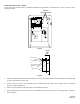
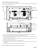
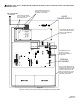
One SP4Z-A/B can be connected to the SP40/2 panel. It is to be mounted inside the panel enclosure onto the backplane in the upper
right hand corner. Two SP4Z-A/B's can be connected to the SPB-160. One SP4Z-A/B can be connected to the SPB-80/4. It is to be
mounted inside the SPB-160 or SPB-80/4 panel on the Splitter Mounting Bracket (SPMB-4Z - purchased separately) mounted over the
24VDC Power Supply (SAPS). The SP4Z-A/B has a maximum power output per zone that cannot exceed what is listed in Table 1.
NOTE: All CAUTIONS and WARNINGS are identified by the symbol
. All warnings are printed in bold capital letters.
WARNING: PLEASE READ THESE INSTRUCTIONS CAREFULLY BEFORE USING THIS PRODUCT. FAILURE TO COMPLY
WITH ANY OF THE FOLLOWING INSTRUCTIONS, CAUTIONS AND WARNINGS COULD RESULT IN IMPROPER APPLICATION,
INSTALLATION AND/OR OPERATION OF THESE PRODUCTS IN AN EMERGENCY SITUATION, WHICH COULD RESULT IN
PROPERTY DAMAGE AND SERIOUS INJURY OR DEATH TO YOU AND/OR OTHERS.
SPECIFICATIONS:
Table 1.
Operating Voltage 25.0V 70.7V
Maximum Output Power Per Zone 40.0W 40.0W
Audio Output Voltage 24VDC
Class A
Standby/Alarm Current at 24VDC 15mA
Class B Maximum Output Power Per Zone 20W 20W
WIRING INSTRUCTIONS:
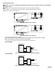
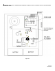
NOTE: The terminal blocks on the SP4Z-A/B are removable. To remove a terminal block, pull the block straight up from the
circuit board as shown in Figure 1. Attach wires to the desired connections, then plug the terminal block back on the board
being careful to match and align the pins.
Figure 1.
Copyright 2003 Wheelock, Inc. All rights reserved.