
Instruction manual


P84205 K
Sheet 3 of 9
MOUNTING INSTRUCTIONS: (SPB-160 and SPB-80/4)
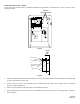
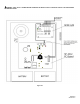
Figure 4 shows the mounting location of the SP4Z-A/B Splitter to the Splitter Mounting Bracket (SPMB-4Z - purchased separately).
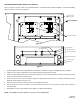
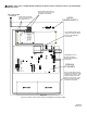
Figure 5 shows the correct mounting procedure.
PS-
PS+
TB1
N
L
SPLITTER COVER
SPLITTER BOARD
(4) #8-32 KEPS NUT
BACKPLATE
(4) #6-32 SCREW
(4) HEX M/F SPACER
(4) LOCKING F SPACER
SPLITTER MTG BRKT
SPLITTER (SP4Z-A/B)
SPLITTER MOUNTING
BRACKET (SPMB-4Z)
24VDC POWER
SUPPLY (SAPS)
Figure 4.
Figure 5.
TROUBLE
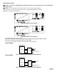
CLASS B WIRING
CLASS A WIRING
ZONE
1
ZONE
2
POWER
24VDC
+
-
Z2
AUD
IN
Z3 Z4
ZONE
1
ZONE
2
ZONE
3
ZONE
4
TROUBLE
POWER
ZONE
ZONE
Z1
Z1
ZONE
CLASS A WIRING
CLASS B WIRING
1
-
24VDC
+
+
AUD
-
IN
+
2
ZONE
ZONEZONE
ZONE
1
2 3
ZONE
4
-
+
-
Z2 Z3
+
-
-
Z4
+
+
-
+
-
+
-
+
-
+
-
1. Mount the Splitter Mounting Bracket (SPMB-4Z) to the SPB-160 or SPB-80/4 according to installation instructions (P84252).
2. Install the 4 nylon Locking Female Spacers to the mounting bracket by pushing them into place.
3. Position the SP4Z-A/B PC board with the terminal blocks pointing to the top of the Audio Booster enclosure and align the mounting
holes on the PC board with the mounting studs.
4. Screw the male end of the 4 Hex M/F Spacers through the SP4Z-A/B PC board and to the 4 Locking Female Spacers on the
SPMB-4Z. Tighten standoffs snug plus ¼ turn.
5. Attach wiring in accordance with the wiring section of this installation instruction.
6. Align the SP4Z-A/B Cover with the holes in the cover spacers and mount the cover using the 4 mounting screws. Tighten the
screws hand tight.
7. Repeat Steps 2 through 6 when installing second splitter in the SPB-160 Audio Booster.
NOTE: One SPMB-4Z mounting bracket can support two SP4Z-A/B splitters.