
Instruction manual


P84205 K
Sheet 8 of 9
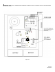
WIRING SPECIFICATIONS:
Cable Size: Accepts #12 - #18 American Wire Gauge (AWG) for single wire connection or #16 - #18 AWG for double wire
connections.
OPERATING INSTRUCTIONS:
TROUBLE
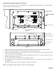
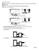
CLASS B WIRING
CLASS A WIRING
ZONE
1
ZONE
2
POWER
24VDC
+
-
Z2
AUD
IN
Z3 Z4
ZONE
1
ZONE ZONE
3
ZONE
4
Z1
2
+
-
+
-
+
-
+
-
+
-
Figure 8.
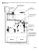
TROUBLESHOOTING PROCEDURES:
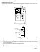
Figure 9 Power and trouble LED's on the SP4Z-A/B Splitter PC board.
1. Insure that the green POWER LED is “ON”. If no LED's are lighted, check the 24VDC input power.
2. Verify wiring is correct.
3. Verify jumpers are correct.
4. If the yellow TROUBLE LED is “ON” an output circuit supervision trouble is indicated. Remove the SP4Z-A/B cover and observe
the 8 yellow LED's as shown in Figure 9 to determine the reason for the trouble.
5. For each SHORT LED “ON”, check the speaker output wiring for that zone for a short or a faulty speaker appliance.
6. For each OPEN LED “ON”, check the speaker wire run for that zone for an open or that the end of line resistor is missing. With the
zone wiring removed from the SP4Z-A/B, a resistance reading on the zone will indicate the 10K Ohm EOLR and the wire
resistance if the circuit is correct.
7. If a zone output does not operate and the green POWER LED is “ON" while the yellow TROUBLE LED is “OFF”, the SP4Z-A/B
splitter has malfunctioned. Replace.
Z3 OPENZ4 SHORT
Z4 OPEN
Z2 OPEN
Z1 OPEN
PWR
TBL
TB1
TB2
TB3
Z1 SHORT Z2 SHORT
Z3 SHORT
Figure 9.