
User Manual

Page 2
CAUTION! DO NOT LOOK DIRECTLY AT THESE LEDS WHILE THEY ARE ON.
MOMENTARY BLINDNESS AND/OR EYE DAMAGE COULD RESULT!
IMPORTANT WARNING!
1. SignalAlert™75 ....PH.1
2. SignalAlert™ PH.2
3. SignalAlert™ PH.3
4. SignalAlert™ PH.4
5. CometFlash® ....PH.1
6. CometFlash® PH.2
7. CometFlash® PH.3
8. CometFlash® PH.4
17. ComAlert™75 .....PH.1
18. ComAlert™ PH.2
19. ComAlert™ PH.3
20. ComAlert™ PH.4
21. LongBurst™ .....PH.1
22. LongBurst™ PH.2
23. LongBurst™ PH.3
24. LongBurst™ .....PH.4
29. SSNF PH.1
30. SSNF PH.2
9. DoubleFlash PH.1
10. DoubleFlash PH.2
11. DoubleFlash PH.3
12. DoubleFlash PH.4
13. SingleFlash PH.1
14. SingleFlash PH.2
15. SingleFlash PH.3
16. SingleFlash PH.4
25. PingPong™ PH.1
26. PingPong™ PH.2
27. PingPong™ PH.3
28. PingPong™ PH.4
31. SingleFlash60.....ALT
32. SingleFlash60.....SIM
33. SingleFlash90.....ALT
34. SingleFlash90.....SIM
35. SingleFlash120....ALT
36. SingleFlash120....SIM
49. DoubleFlash 120 ...ALT
50. DoubleFlash 120 ...SIM
51. PingPong™ 120....ALT
52. PingPong™ 120 ....SIM
53. TripleFlash™75 ...ALT
54. TripleFlash 75....SIM
55. TripleFlash 120 . . ALT
56. TripleFlash 120...SIM
57. SigAlertCal.™.....ALT
58. SigAlertCal.™.....SIM
59. Action1 ..........ALT
60. Action1 ..........SIM
61. Action2 ..........ALT
62. Action2 ..........SIM
63. CalScan™......Alt/Sim
65. SteadyFlash 60
66. SteadyFlash 75
67. SteadyFlash 90
68. SteadyFlash 120
69. Steady & Steady
37. SingleFlash300.....ALT
38. SingleFlash300.....SIM
44. ActionFlash™ 50 ....SIM
45. ActionFlash™ 150 ...ALT
46. ActionFlash™ 150 ...SIM
47. ModuFlash™ .......ALT
48. ModuFlash™ .......SIM
64. ActionScan™ ....Alt/Sim
9 DoubleFlash 150 ....ALT
40 DoubleFlash 150 SIM
41 ComAlert™150 ALT
42 ComAlert™150 SIM
43 ActionFlash™ 50 ....ALT
75....
75....
75....
75
75....
75....
75....
75 .....
75 .....
75 .....
75
75.....
75.....
75
75 .........
75 .........
75 ...
75 ...
75 ...
75 ...
75....
75....
75....
75....
75 ....
75 ....
75 ....
75 ....
3.
. ....
. .....
. .....
.
™
™
™
Split Lighthead Patterns:
1. SignalAlert™75 ....PH.1
2. SignalAlert™ PH.2
. CometFlash® PH.2
. DoubleFlash PH.2
. SingleFlash PH.1
. SingleFlash PH.2
9. ComAlert™75 .....PH.1
1 . ComAlert™ PH.2
. LongBurst™ .....PH.1
2. LongBurst™ PH.2
. PingPong™ PH.1
. PingPong™ PH.2
. CometFlash® ....PH.1
. DoubleFlash PH.1
18. SingleFlash 300
19
. ActionFlash™
22. ActionFlash™ 2
23. ModuFlash™
24. ActionScan™15. SingleFlash 60
16. SingleFlash 90
17. SingleFlash 120
25. Steady
DoubleFlash 150
ComAlert™15075....
375
4 75....
5 75....
6 75....
7 75.....
8 75.....
0 75 .....
11 75
1 75.....
13 75.....
14 75.....
.
20.
21 1
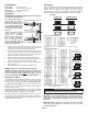
Standard Lighthead Patterns:
NOTE: BOLD = CA Title XIII Compliant Pattern = SYNC PatternItalic
NOTE: BOLD = CA Title XIII Compliant Pattern
= SYNC PatternItalic
PHASE 1
LEFT
RIGHT
side lights up and
with side.alternates
then
then
ON OFF
ONOFF
ON OFF
PHASE 2
RIGHT
LEFT
side lights up and
with side.alternates
then
then
ON OFF
ONOFF
ONOFF
PHASE 3
BOTH sides flash together
(ON-OFF-ON).
then
then
ON ON
ON ON
OFFOFF
PHASE 4
BOTH sides flash together
(OFF-ON-OFF).
then
then
ON ON
OFFOFF
OFFOFF
Specifications:
Input Voltage: 12.8 VDC +/- 20%
Input Current: Peak - 400ma / Avg - 160ma
Sync Phase: Phase I & II @ 400ms
Input Scan-Lock™: +12 VDC
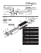
Installation:
IMPORTANT! The lightbar should be located a minimum of
16" from any radio antennas!
Note: When routing wires, it is
important that you choose a
path that will keep the wires
away from any excessive heat
or any vehicle equipment that
could compromise the integrity
of the wires (ex. trunk lids, door
jams, etc.).
Caution: Permanent mounting
of this product will require
drilling. It is absolutely
necessary to make sure that no
other vehicle components
could be damaged by this
process. Check both sides of
the mounting surface before starting. If damage is likely, select a
different mounting location.
1. Position the unit in its proposed mounting location. Draw a pencil
line onto the mounting surface along the top and bottom of the
extrusion and a “centerline” centered between the two.
2. Two 1/4” holes are required to mount this unit. These holes may
be located anywhere along the horizontal centerline that you drew
in step one. It’s best to locate the holes as far apart as possible.
Mark the hole location onto the mounting surface.
3. Using a 1/4” drill bit, drill a hole in the areas scribed in step 2.
4. Insert the two hex-head mounting bolts (included) into one of the 3
channels in the housing. There is a hole in each channel.
5. Align these bolts with the 2 mounting holes and insert them into
the mounting holes.
6. Install an elastic stop nut onto each bolt and tighten firmly.
Wiring: Refer to the wiring diagram on the next page.
WARNING: All customer supplied wires that connect to the positive
terminal of the battery must be sized to supply at least 125% of the
maximum operating current and FUSED
at the battery to carry that
load. DO NOT USE CIRCUIT BREAKERS WITH THIS PRODUCT!
Scan-Lock™ (Blue)
This lighthead has 25 flash patterns (69 patterns for Split-LED) some of
which are available in 2 or 4 modes; Phases 1, 2, 3 or 4 (See SYNC).
The patterns are changed with the BLUE wire. With the lighthead on:
To advance to the next pattern, apply +12 VDC to the BLUE wire for
less than 1 second. To cycle backwards to previous patterns, apply +12
VDC for more than 1 second.
To reset to the factory default pattern, turn off power to the lighthead.
While applying +12 VDC to the BLUE wire, turn the lighthead back on.
Continue to apply voltage to the BLUE wire for 5 seconds.
With SYNC, all lightheads configured to display the Phase 1 mode of a
given pattern will flash simultaneously. Any lightheads configured to
display the Phase 2 mode of a pattern, will alternate with any Phase 1
lightheads with the same pattern.
Sync (Grey)
To sync two lightheads, configure both lightheads to display the same Phase
1 pattern. With the power off, connect the GREY wire from each lighthead
together. When the lightheads are activated, their patterns will be
synchronized. To configure the two lightheads to alternate their patterns,
advance the pattern of either lighthead to Phase 2 of the current pattern.
Phase 1
DRIVER SIDE
EXAMPLE:
Phase 1
Phase 2
PASSENGER SIDE
Phase 2
Phase 2
Phase 1
IMPORTANT! It is the responsibility of the installation technician to
make sure that the installation and operation of this product will not
interfere with or compromise the operation or efficiency of any vehicle
equipment!
IMPORTANT! Before returning the vehicle to active service, visually
confirm the proper operation of this product, as well as all vehicle
components/equipment.
MOUNTING
SURFACE
#10-24 ELASTIC
STOP NUT
(
QTY 2
)
Extrusion end view (without end cap)
MOUNTING
SURFACE
MOUNTING
SURFACE
Mount to any 1
of 3 channels
in the extrusion
#10-24
X3/4"
HEX
HEAD
(
QTY 2
)