
User Manual

Page 2
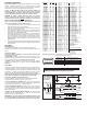
LED Color
3A Fuse*
*5A for Scenelight
To +12VDC
To +12VDC
To +12VDC
To +12VDC
To Ground
To Ground
SYNC
M9
Lighthead
(5-Wire)
M9
Lighthead
(2-Wire)
BLACK
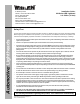
MOUNTING DIMENSIONS
9.062"
4.531"
0.25"
0.625"
0.25"
WIRING DIAGRAM
LED Color
M
O
U
N
T
I
N
G
S
U
R
F
A
C
E
#8 x 1"
PPHSMS
M9 Assembly
Slotted Hole
Screw Grommet
Gasket Note -
Use the gasket
on flat, smooth surfaces
. For diamond plate,
use optional gasket,
P/N 38-016B624-01
included
only
WHT/VIO
MOM. SW.
SP/ST
1A Fuse
3A Fuse
1A Fuse
SP/ST
VIO
BLACK
GREY
SP/ST
Pattern
Seq
Phase
1 SignalAlert™ Solid PH.1
2 SignalAlert Solid PH.2
3 SignalAlert L/R PH.1
4 SignalAlert L/R PH.2
5 SignalAlert T/B PH.1
6 SignalAlert T/B PH.2
7 SignalAlert I/O PH.1
8 SignalAlert I/O PH.2
9 SignalAlert Diag PH.1
10 SignalAlert Diag PH.2
21 DoubleFlash 75 Solid PH.1
22 DoubleFlash 75 Solid PH.2
23 DoubleFlash 75 L/R PH.1
24 DoubleFlash 75 L/R PH.2
25 DoubleFlash 75 T/B PH.1
26 DoubleFlash 75 T/B PH.2
27 DoubleFlash 75 I/O PH.1
28 DoubleFlash 75 I/O PH.2
29 DoubleFlash 75 Diag PH.1
30 DoubleFlash 75 Diag PH.2
31 SingleFlash 75 Solid PH.1
32 SingleFlash 75 Solid PH.2
33 SingleFlash 75 L/R PH.1
34 SingleFlash 75 L/R PH.2
35 SingleFlash 75 T/B PH.1
36 SingleFlash 75 T/B PH.2
37 SingleFlash 75 I/O PH.1
38 SingleFlash 75 I/O PH.2
39 SingleFlash 75 Diag PH.1
40 SingleFlash 75 Diag PH.2
11 CometFlash®75 Solid PH.1
12 CometFlash 75 Solid PH.2
13 CometFlash 75 L/R PH.1
14 CometFlash 75 L/R PH.2
15 CometFlash 75 T/B PH.1
16 CometFlash 75 T/B PH.2
17 CometFlash 75 I/O PH.1
18 CometFlash 75 I/O PH.2
19 CometFlash 75 Diag PH.1
20 CometFlash 75 Diag PH.2
41 ComAlert™ 75 Solid PH.1
42 ComAlert 75 Solid PH.2
43 ComAlert 75 L/R PH.1
44 ComAlert 75 L/R PH.2
45 ComAlert 75 T/B PH.1
46 ComAlert 75 T/B PH.2
47 ComAlert 75 I/O PH.1
48 ComAlert 75 I/O PH.2
49 ComAlert 75 Diag PH.1
50 ComAlert 75 Diag PH.2
51 LongBurst™ 75 Solid PH.1
52 LongBurst 75 Solid PH.2
53 LongBurst 75 L/R PH.1
54 LongBurst 75 L/R PH.2
55 LongBurst 75 T/B PH.1
56 LongBurst 75 T/B PH.2
57 LongBurst 75 I/O PH.1
58 LongBurst 75 I/O PH.2
59 LongBurst 75 Diag PH.1
60 LongBurst 75 Diag PH.2
61 PingPong™ 75 Solid PH.1
62 PingPong 75 Solid PH.2
63 PingPong 75 L/R PH.1
64 PingPong 75 L/R PH.2
65 PingPong 75 T/B PH.1
66 PingPong 75 T/B PH.2
67 PingPong 75 I/O PH.1
68 PingPong 75 I/O PH.2
69 PingPong 75 Diag PH.1
70 PingPong 75 Diag PH.2
PH.1
72 SingleFlash 60 L/R PH.1
73 SingleFlash 60 T/B PH.1
74 SingleFlash 60 I/O PH.1
75 SingleFlash 60 Diag PH.1
76 SingleFlash 90 Solid PH.1
77 SingleFlash 90 L/R PH.1
78 SingleFlash 90 T/B PH.1
79 SingleFlash 90 I/O PH.1
80 SingleFlash 90 Diag PH.1
81 SingleFlash 120 Solid PH.1
82 SingleFlash 120 L/R PH.1
83 SingleFlash 120 T/B PH.1
84 SingleFlash 120 I/O PH.1
85 SingleFlash 120 Diag PH.1
86 SingleFlash 300 Solid PH.1
87 SingleFlash 300 L/R PH.1
88 SingleFlash 300 T/B PH.1
89 SingleFlash 300 I/O PH.1
90 SingleFlash 300 Diag PH.1
91 DoubleFlash 150 Solid PH.1
92 DoubleFlash 150 L/R PH.1
93 DoubleFlash 150 T/B PH.1
94 DoubleFlash 150 I/O PH.1
95 DoubleFlash 150 Diag PH.1
96 ComAlert™150 Solid PH.1
97 ComAlert 150 L/R PH.1
98 ComAlert 150 T/B PH.1
99 ComAlert 150 I/O PH.1
100 ComAlert 150 Diag PH.1
101 ActionFlash™50 Solid PH.1
102 ActionFlash 50 L/R PH.1
103 ActionFlash 50 T/B PH.1
104 ActionFlash 50 I/O PH.1
105 ActionFlash 50 Diag PH.1
106 ActionFlash 150 Solid PH.1
107 ActionFlash 150 L/R PH.1
108 ActionFlash 150 T/B PH.1
109 ActionFlash 150 I/O PH.1
110 ActionFlash 150 Diag PH.1
71 SingleFlash 60 Solid
111 ModuFlash™ Solid
112 ModuFlash L/R
113 ModuFlash T/B
114 ModuFlash I/O
115 ModuFlash Diag
146 Cylon SLOW
147 Cylon MEDIUM
148 Cylon FAST
149 Cylon VARIABLE
150 Cylon MEDIUM w/SOLID
151 PinWheel SLOW
152 PinWheel MEDIUM
153 PinWheel FAST
154 PinWheel VARIABLE
155 PinWheel MEDIUM w/Solid
157 ActionScan™
158 SignalAlert™ Steady
116 DoubleFlash 120 Solid
117 DoubleFlash 120 L/R
118 DoubleFlash 120 T/B
119 DoubleFlash 120 I/O
120 DoubleFlash 120 Diag
121 PingPong™120 Solid
122 PingPong 120 L/R
123 PingPong 120 T/B
124 PingPong 120 I/O
125 PingPong 120 Diag
126 TripleFlash™75 Solid
127 TripleFlash 75 L/R
128 TripleFlash 75 T/B
129 TripleFlash 75 I/O
130 TripleFlash 75 Diag
131 TripleFlash 120 Solid
132 TripleFlash 120 L/R
133 TripleFlash 120 T/B
134 TripleFlash 120 I/O
135 TripleFlash 120 Diag
136 Action SF 60/120 Solid
137 Action SF 60/120 L/R
138 Action SF 60/120 T/B
139 Action SF 60/120 I/O
140 Action SF 60/120 Diag
141 Action SF 60/TF 120 Solid
142 Action SF 60/TF 120 L/R
143 Action SF 60/TF 120 T/B
144 Action SF 60/TF 120 I/O
145 Action SF 60/TF 120 Diag
156 CalScan
*
*159 Steady
*No low power for this pattern.
M9 Sequencing & Phasing: The M9 lighthead has 8 sets of 3 LEDs. These sets cycle
through the 5 sequences shown below.
SYNCITALIC =
BOLD = CA Title XIII Compliant
L/R = Left/Right
T/B = Top/Bottom
I/O = In/Out
Sequences Operation of LED sets
Solid
T
Left to Right (L/R)
op to Bottom (T/B)
In and Out (I/O)
Diagonal (Diag)
Alternates with
Alternates with
Alternates with
Alternates with
Alternates with
All On
1-2-5-6
1-2-3-4
2-3-6-7
1-2-7-8
All Off
3-4-7-8
5-6-7-8
1-4-5-8
5-6-3-4
1
87
2
5
43
6
CAUTION! DO NOT LOOK DIRECTL Y A T THESE LEDS WHILE THEY ARE ON.
MOMENT AR Y BLINDNESS AND/OR EYE D AMAGE COULD RESUL T!
IMPORTANT WARNING!
Installation and Wiring:
External Flasher Models: This product draws significantly less current than a
standard incandescent automotive bulb. If your flasher does not operate
properly, it may be necessary to replace your flasher module with a Whelen®
flasher module. Contact your sales representative for application.
Caution: Permanent mounting of this product will require drilling. It is
absolutely necessary to make sure that no other vehicle components
could be damaged by this process. Check both sides of the mounting
surface before starting. If damage is likely, select a different location.
WARNING! All customer supplied wires that connect to the positive
terminal of the battery must be sized to supply at least 125% of the
maximum operating current and FUSED
at the battery to carry that load.
DO NOT USE CIRCUIT BREAKERS WITH THIS PRODUCT!
NOTE: The color of the Positive Wire is determined by the color of the
LED. In this manual, RED is used as a reference color.
1. Using the dimensions shown, mark the 2 mounting hole locations and wire
access hole location onto the mounting surface.
2. Drill the two, 0.250” diameter mounting holes and a 0.625” (minimum) wire
access hole into the mounting surface.
3. Place the appropriate gasket into position on the rear of the M9 assembly
(see Gasket Note). Insert the slotted hole screw grommet through the
mounting holes on the M9/Gasket assembly.
4. Feed the M9 wires through the wire access hole in the mounting surface.
Press the M9/Gasket/Grommet assembly onto its mounting location so
that it is flat against the mounting surface. With the assembly in position
and using the hardware provided, tighten the mounting screws until the
lighthead assembly is drawn firmly against the mounting surface. DO NOT
OVERTIGHTEN!
5. Using appropriately sized wires (minimum 18 AWG), extend the M9 wires
to their designated connections. Refer to the diagram below for wiring and
fusing information.
Operation:
Flash Mode / RED:
Apply +VBAT to the RED wire to activate the lighthead in “flash mode”.
With flash mode activated, you may change the flash pattern using Scan-
Lock™.
Low Power / VIOLET:
The type of switch used depends on how the operator wishes the Low
Power feature to function:
Latching Mode: By applying +VBAT to the VIO wire for less than 1 sec., the
lighthead is “latched” into low power. The unit must be turned off and then back
on to restore normal operation. (A momentary switch is preferred)
Level Mode: Applying +VBAT to the VIO wire for more than 1 sec. holds the
lighthead in low power mode until voltage is removed. (A toggle switch is
preferred)
SYNC / GREY
To SYNC two lightheads, configure both lightheads to display the same Phase 1
(Simultaneous) pattern. Turn the power off and connect the GREY wire from
each lighthead together. When the lightheads are activated their patterns will be
synchronized. To configure two lightheads to alternate their patterns, advance
the pattern of either lighthead to Phase 2 (Alternating) of the current pattern.
NOTE: You can also program the 2 banks of LEDs inside the lighthead to
flash in different configurations (See M9 Sequencing and Phasing).
Scan-Lock™ / WHT/VIO / Flash Pattern Selection:
This feature allows the user to select from several available flash patterns.
The lighthead must be switched on for Scan-Lock™ to work.
TO CYCLE THROUGH ALL PATTERNS: Apply +VBAT to the WHT/VIO wire
for less than 1 second and release. To cycle backward through patterns apply
+VBAT to the WHT/VIO wire for over 1 second and release.
TO SET A PATTERN AS DEFAULT: Allow the pattern to run for more than 5
seconds. The lighthead will flicker slightly when the pattern locks in. This flicker
may be difficult to see with some patterns. The lighthead will now display this
pattern when activated.
TO RESET TO THE FACTORY DEFAULT PATTERN: Turn off power. While
applying +VBAT to the WHT/VIO wire, turn power on. This will reset the
lighthead to it’s factory default flash pattern.
IMPORTANT! It is the responsibility of the installation technician to make
sure that the installation and operation of this product will not interfere
with or compromise the operation or efficiency of any vehicle equipment!