3977625v09c27 4/1/99 4:45 PM Page 1 240-Volt Compact Electric Dryer A Note to You ....................2 Dryer Safety........................3 Installation Instructions ........................5 Parts and Features ..........23 Using Your Dryer ............24 Starting your dryer ........…24 End of cycle signal ...........25 Loading ............................25 Selecting the right cycle and setting…… ............….25 Caring for Your Dryer ................................28 Troubleshooting ..............
3977625v09c27 4/1/99 4:45 PM Page 2 A Note to You Thank you for buying a WHIRLPOOL® appliance. The Whirlpool Brand is committed to designing quality products that consistently perform for you to make your life easier. To ensure that you enjoy years of trouble-free operation, we developed this Use and Care Guide. It is full of valuable information about how to operate and maintain your appliance properly and safely. Please read it carefully.
977625v09c27 4/1/99 4:45 PM Page 3 Dryer Safety Your safety and the safety of others is very important. We have provided many important safety messages in this manual and on your appliance. Always read and obey all safety messages. This is the safety alert symbol. This symbol alerts you to hazards that can kill or hurt you and others. All safety messages will be preceded by the safety alert symbol and the word “DANGER” or “WARNING.
3977625v09c27 4/1/99 4:45 PM Page 4 DRYER SAFETY IMPORTANT SAFETY INSTRUCTIONS WARNING: To reduce the risk of fire, electric shock, or injury to persons when using the dryer, follow basic precautions, including the following: • Do not repair or replace any • Read all instructions before part of the dryer or attempt any using the dryer. servicing unless specifically • Do not place items exposed to recommended in this Owner’s cooking oils in your dryer.
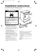
3977625v09c27 4/1/99 4:45 PM Page 5 Installation Instructions Read the “Dryer Safety” section of your dryer’s Use and Care guide, and completely read these installation instructions before beginning installation. Before starting installation 203⁄4" ➤ ➤ ➤ wWARNING 31" ➤ 237⁄8" ➤ • Check location where dryer will be in-stalled. Proper installation is your responsibility. The dryer must not be installed or stored in an area where it will be exposed to water and/or weather.
3977625v09c27 4/1/99 4:45 PM Page 6 INSTALLATION INSTRUCTIONS How to install your dryer Now that you’ve unpacked your dryer, check to be sure you have removed the parts bag from the drum. Remove the tape that holds the drum to the cabinet. Move the drum by hand to make certain all tape has been removed. Next, wipe the interior of the drum thoroughly with a damp cloth before using the dryer. Installation To install your dryer, you will need the tools shown.
3977625v09c27 4/1/99 4:45 PM Page 7 INSTALLATION INSTRUCTIONS Installing the leveling legs Leveling your dryer correctly will reduce operating noise and provide improved drying performance. WARNING Excessive Weight Hazard Use two or more people to move and install dryer. Failure to do so can result in back or other injury. To install leveling legs: 1. Take two of the cardboard corners from the carton. Place them on the floor in back of the dryer. 2. Firmly grasp the body of the dryer.
3977625v09c27 4/1/99 4:45 PM Page 8 INSTALLATION INSTRUCTIONS Electrical Requirements A three-wire or four-wire, single phase 120/240-volt, 60-Hz., AC-only, electrical supply is required on a separate 30-ampere circuit, fused on both sides of the line. A time-delay fuse or circuit breaker is recommended. This dryer is manufactured with the 3-wire, frame-grounding conductor connected to the NEUTRAL (center) of the wiring harness of the terminal block.
3977625v09c27 4/1/99 4:45 PM Page 9 INSTALLATION INSTRUCTIONS Three-Wire Electrical Connection to Receptacle wWARNING Fire Hazard Use a new UL approved 30 ampere power supply cord. Use a UL approved strain relief. Disconnect power before making electrical connections. Connect neutral wire (white or center wire) to center terminal (silver). Ground wire (green or bare wire) must be connected to green ground connector. Connect remaining 2 supply wires to remaining 2 terminals (gold).
3977625v09c27 4/1/99 4:45 PM Page 10 INSTALLATION INSTRUCTIONS 1. Disconnect power. Terminal block cover Hold-down screw 2. Remove hold-down screw and terminal block cover. 3. Attach a 3⁄4-inch, U.L.-listed, strain relief to the hole below terminal block opening. Strain relief should have a tight fit with dryer cabinet and be in a horizontal position. Put the power supply cord through the strain relief. External ground connector Center silver-colored terminal block screw Neutral wire (white) 4.
3977625v09c27 4/1/99 4:45 PM Page 11 INSTALLATION INSTRUCTIONS Three-Wire Electrical Connection (Direct Wire) wWARNING GROUNDING INSTRUCTIONS This appliance must be connected to a grounded metal, permanent wiring system; or an equipment-grounding conductor must be run with the circuit conductors and connected to the equipment-grounding terminal or lead on the appliance. Fire Hazard Use 10 gauge solid copper wire. Use a UL approved strain relief. Disconnect power before making electrical connections.
3977625v09c27 4/1/99 4:46 PM Page 12 INSTALLATION INSTRUCTIONS 2. Remove hold-down screw and terminal block cover. 3. Attach a 3⁄4-inch, U.L.-listed, strain relief to the hole below terminal block opening. Strain relief should have a tight fit with dryer cabinet and be in a horizontal position. Put the direct wire cable through the strain relief.
3977625v09c27 4/1/99 4:46 PM Page 13 INSTALLATION INSTRUCTIONS 5. Connect the other two wires to outer terminal block screws using the same method(s) described in step 4. Tighten all terminal block screws firmly. 6. Tighten the strain relief screws. 7. Insert tab of terminal block cover into slot of the dryer rear panel. Secure cover with hold-down screw. NOTE: If local codes do not permit the connection of a frame-grounding conductor to the neutral wire, see the instructions for “Alternate Connection.
3977625v09c27 4/1/99 4:46 PM Page 14 INSTALLATION INSTRUCTIONS Make Four-Wire Electrical Connection to Receptacle wWARNING Fire Hazard Use a new UL approved 30 ampere power supply cord. Use a UL approved strain relief. Disconnect power before making electrical connections. Connect neutral wire (white or center wire) to center terminal (silver). Ground wire (green or bare wire) must be connected to green ground connector. Connect remaining 2 supply wires to remaining 2 terminals (gold).
3977625v09c27 4/1/99 4:46 PM Page 15 INSTALLATION INSTRUCTIONS 1. Disconnect power. 2. Remove hold-down screw and terminal block cover. 3. Attach a 3⁄4-inch, U.L.-listed, strain relief to the hole below terminal block opening. Strain relief should have a tight fit with dryer cabinet and be in a horizontal position. Put the power supply cord through the strain relief. 4. Remove the center terminal block screw. Remove the neutral grounding wire (green/yellow wire) from external grounding screw.
3977625v09c27 4/1/99 4:46 PM Page 16 INSTALLATION INSTRUCTIONS Four-Wire Electrical Connection (Direct Wire) wWARNING Fire Hazard Use 10 gauge solid copper wire. Use a UL approved strain relief. Disconnect power before making electrical connections. Connect neutral wire (white or center wire) to center terminal (silver). Ground wire (green or bare wire) must be connected to green ground connector. Connect remaining 2 supply wires to remaining 2 terminals (gold).
3977625v09c27 4/1/99 4:46 PM Page 17 INSTALLATION INSTRUCTIONS 3. Attach a 3⁄4-inch, U.L.-listed, strain relief to the hole below terminal block opening. Strain relief should have a tight fit with dryer cabinet and be in a horizontal position. Put the direct wire cable through the strain relief. 4. Remove the center terminal block screw. Remove the neutral grounding wire (green/yellow wire) from external grounding screw.
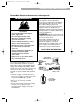
3977625v09c27 4/1/99 4:46 PM Page 18 INSTALLATION INSTRUCTIONS Exhaust requirements Your dryer must be properly vented to achieve maximum drying efficiency. WARNING: To reduce the risk of fire, this dryer MUST BE EXHAUSTED OUTDOORS. • Do not exhaust dryer into a chimney, a wall, a ceiling, or a concealed space of a building. • The diameter of the heavy metal vent must be 4-in. • Do not use an exhaust hood with a magnetic latch. wWARNING Fire Hazard Use a heavy metal vent. Do not use a plastic vent.
3977625v09c27 4/1/99 4:46 PM Page 19 INSTALLATION INSTRUCTIONS Use duct tape to seal all joints. Do not use screws to secure vent. Lint may catch on screws. Use 4-inch heavy metal vent. Do not kink or crush flexible metal vent. It must be fully extended to allow adequate exhaust air to flow. Check vent after installation. Better Good Exhaust airflow Use the straightest path possible when routing the exhaust vent. Use the fewest number of elbows and turns.
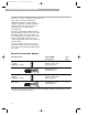
3977625v09c27 4/1/99 4:46 PM Page 20 INSTALLATION INSTRUCTIONS Determining vent length NOTE: Check periodically to ensure that the outside exhaust hood is not blocked. The maximum length of the exhaust system depends upon: • The type of vent (heavy or flexible metal). • The number of elbows (90° turns) used. To determine maximum vent length: 1. See the Exhaust Hood Type chart that matches your hood type for the maximum vent lengths you can use.
3977625v09c27 4/1/99 4:46 PM Page 21 INSTALLATION INSTRUCTIONS Recessed area and closet installation NOTE: Check codes requirements. Some codes limit or do not permit installation of clothes dryers in garages, closets, mobile homes, or sleeping quarters. Contact your local building inspector. • This dryer may be installed in a recessed area or closet. If closet door is installed, the minimum unobstructed air openings in top and bottom are required.
3977625v09c27 4/1/99 4:46 PM Page 22 INSTALLATION INSTRUCTIONS Mobile home installation NOTE: Check codes requirements. Some codes limit or do not permit installation of clothes dryers in garages, closets, mobile homes, or sleeping quarters. Contact your local building inspector. • The exhaust vent must be securely fastened to a non-combustible portion of the mobile home structure and must not terminate beneath the mobile home.
3977625v09c27 4/1/99 4:46 PM Page 23 Parts and Features Cycle and temperature control knob (p. 26) Start button (p. 24) Model and serial number label (p. 2) END • PUSH LE 3 CYC AL LE SIGN OF CYC DUTY HEAVY Lint screen (p.
3977625v09c27 4/1/99 4:46 PM Page 24 Using Your Dryer WARNING Explosion Hazard Keep flammable materials and vapors, such as gasoline, away from dryer. Do not dry anything that has ever had anything flammable on it (even after washing). Failure to follow these instructions can result in death, explosion, or fire. wWARNING Fire Hazard No washer can completely remove oil. Do not dry anything that has ever had any type of oil on it (including cooking oils).
3977625v09c27 4/1/99 4:46 PM Page 25 USING YOUR DRYER End of cycle signal The dryer sounds a signal to let you know when the cycle is finished. The signal is not adjustable and cannot be turned off. The signal is helpful when you are drying permanent press, synthetics, and other items that should be taken out as soon as the dryer stops. Loading Loading suggestions This table shows the maximum load you can place in your compact dryer. Expect longer drying times.
3977625v09c27 4/1/99 4:46 PM Page 26 USING YOUR DRYER Automatic Permanent Press/ Regular Cycle 10 20 30 AIR R F F O 30 40 50 6 20 TIMED DRYING 0 O F F LE SS PER M. MO / REG. ESS PR RE O F F AI 0 30 20R 10 O F F 03 10 2 TIM0 40 F AIR 10 20 30 70 80 60 NG YI O F 5 0 ED DR The Air cycle has no heat. Use this unheated cycle to fluff or air dry bedding, plastic tablecloths, foam pillows, sneakers, etc. See page 27 for more information about the Air cycle. 1 R Air cycle O F F .
3977625v09c27 4/1/99 4:46 PM Page 27 USING YOUR DRYER Selecting the right cycle and setting TYPE OF LOAD Cottons and linens Extra heavy–Bedspreads, mattress pads, quilts Heavyweight–Towels, jeans, corduroys, work clothes Mediumweight–Sheets, cotton underwear, diapers Lightweight–Batistes, organdies, lingerie CYCLE Timed Drying Perm. Press/Reg. TIME (minutes) 45-55 Perm. Press/Reg. Perm. Press/Reg.
3977625v09c27 4/1/99 4:46 PM Page 28 Caring for Your Dryer Cleaning the lint screen Every load cleaning As needed cleaning The lint screen is located inside the dryer drum, on the back wall. Clean it before starting each load. A screen blocked by lint can increase drying time. Laundry detergents and fabric softeners can cause a residue buildup on the lint screen. Clean the lint screen with a nylon brush every six months or more frequently if it becomes clogged due to a residue buildup. To clean: 1.
3977625v09c27 4/1/99 4:46 PM Page 29 CARING FOR YOUR DRYER Cleaning the dryer interior Garments which contain unstable dyes, such as denim blue jeans or brightly colored cotton items, may discolor the dryer interior. These stains are not harmful to your dryer and will not stain future loads of clothes. It is helpful to dry unstable dye items inside out to prevent dye transfer. To clean dryer drum: 1. Make a paste with powdered laundry detergent and very warm water. 2. Apply paste to a soft cloth.
3977625v09c27 4/1/99 4:46 PM Page 30 Troubleshooting Common drying problems PROBLEM CAUSE SOLUTION Not drying satisfactorily • Lint screen is clogged with lint. • Clean lint screen. • Restricted air movement. • Run dryer for 5-10 minutes. Hold Exhaust vent or outside exhaust hand under outside exhaust hood to hood is clogged with lint. check air movement.
3977625v09c27 4/1/99 4:46 PM Page 31 TROUBLESHOOTING Common drying problems (cont) PROBLEM CAUSE SOLUTION Lint in load • Lint screen is clogged. • Clean lint screen. Check for air movement. • Improper sorting. • Sort lint givers from lint takers and sort by color. • Load is too big or heavy. • Dry smaller loads so lint can be carried to the lint screen. • Load is overdried. • Use correct dryer settings for fabric. Overdrying can cause lint-attracting static (see “Using Your Dryer”).
3977625v09c27 4/1/99 4:46 PM Page 32 Assistance or Service If you need assistance or service Call our Consumer Assistance Center at 1-800-253-1301. Our consultants are available to assist you. When calling: Please know the purchase date, and the complete model and serial number of your appliance (see “A Note to You” section). This information will help us better respond to your request.
3977625v09c27 4/1/99 4:46 PM Page 36 WHIRLPOOL Dryer Warranty ® LENGTH OF WARRANTY COVERED BY WARRANTY FULL ONE-YEAR WARRANTY FROM DATE OF PURCHASE FSP® replacement parts and repair labor to correct defects in materials or workmanship. Service must be provided by a Whirlpool designated service company. NOT COVERED BY WARRANTY A. Service calls to: 1. Correct the installation of your dryer, including venting. Heavy 4-inch metal exhaust vent must be used.