
Range User Manual


D
n
Provide a gas supply line of 3/4” rigid
Recommended
grounding method
pipe to the range location. -A smaller size-
pipe on long runs may result in insufficient
gas supply. Pipe-joint compounds made for
use with L.P. gas must be used. With L.P. gas,
piping or tubing size can be l/2” minimum.
L.P. gas suppliers usually determine the size
and materials used on the system.
E
I
n
If local codes permit, a new
A.G.A.design-certified, 4 - 5 foot long,1 12” or
3/4” I.D., flexible metal appliance connector
is recommended for connecting this range
to the gas supply line. Do Not kink or
damage the flexible tubing when moving the
range. A l/2-inch male pipe thread is
needed for connecti
regulator female pipe thre
L
rm The supply line shall be equipped with
an approved shutoff valve. This valve should
be located in the same room as the range
and should be in a location that allows ease
of opening and closing. Do Not block
access to shutoff valve.
G
n
If rigid pipe is u
line, a combination of pi
used to obtain an in-line connec
range. All strains must be removed from the
supply and fuel lines so range will be level
and in line.
H
n
The reaulator must be checked at
a minimum of 1 -inch water column above
the set pressure. The inlet pressure to the
regulator should be as follows for operation:
NATURAL GAS:
Set pressure 5 inches
Maximum pressure 14 inches
L.P. GAS:
Set pressure 11 inches
Maximum pressure 14 inches
I
n
Line pressure testing:
Testing above l/2 lb psi (gauge)
The range and its individual shutoff valve
must be disconnected from the gas supply
piping system during any pressure testing of
that system at test pressures greater than
l/2 psig (3.5 kPa).
Testing at l/2 lb psi (gauge)
The range must be isolated from the gas
supply piping system by closing its individual
manual shutoff valve during any pressure
testing of the gas supply piping system at
test pressures equal to or less than l/2 psig
(3.5 kPa).
Electrical
Requirements
Electrical Shock Hazard
. Electrical ground is required on this
appliance.
. Improper connection of the equipment-
grounding conductor can result in fire,
electrical shock, or other personal
injury.
. Check with a qualified electrician if you
are in doubt as to whether the
appliance is properly grounded.
l
Do Not modify the power supply cord
plug. If it does not fit the outlet, have a
proper outlet installed by a qualified
electrician.
l
Do Not use an extension cord with this
appliance.
l
Do Not have a fuse in the neutral or
grounding circuit. A fuse in the neutral
or grounding circuit could result in an
electrical shock.
Failure to follow these instructions could
result in a fire, electrical shock or other
personal injury.
A 120-volt, 60-Hz, AC-only, 15-ampere, fused
electrical supply is required. A time-delay
fuse or circuit breaker is recommended. It is
recommended that a separate circuit
serving only this appliance be provided.
Electronic ignition systems operate within
wide voltage limits, but proper grounding
and polarity are necessary. In addition to
checking that the outlet provides 120-volt
power and is correctly grounded, the outlet
must be checked by a qualified electrician
to see if it is wired with correct polarity.
The wiring diagram is found on a separate
sheet in the literature package. The wiring
diagram can also be found on the back of
the range.
DO NOT, UNDER ANY CIRCUMSTANCES,
REMOVE THE POWER SUPPLY CORD
GROUNDING PRONG.
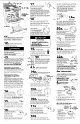
For personal safety, this appliance is
equipped with a power supply cord having
a 3-prong grounding plug. To minimize
possible shock hazard, the cord must be
plugged into a mating 3-prong, grounding-
type wall receptacle, grounded in
accordance with the National Electrical
Code, ANSVNFPA 70-latest edition* and ~;~#“s-h/pe
all local codes and ordinances. (See
wall receptacle
Figure 1.) If a mating wall
receptacle is not available, it grou
is the personal responsibility
and obligation of the
customer to have a
properly grounded, 3-
prong wall receptacle
installed by a qualified
electrician.
grounding
prow
Now start...
With range in kitchen.
I
n
Remove shipping materials, tape
and protective film from range. Keep
cardboard shipping base under range.
Remove oven racks and shipping materials
from inside oven.
2
n
Adjust the leveling legs to a point
where the range base does not touch the
floor.
l
To prevent tipping, install range anti-tip
bracket.
l
Anti-tip bracket must be attached to a
wood or metal wall stud, or concrete or
concrete block wall.
l
Do Not attach anti-tip bracket to a
cabinet.
l
Save these Installation Instructions. If
range is moved to a new location, the
anti-tip bracket must be reinstalled in
the new location.
c
3
n
To mount anti-tip bracket to wood or
metal wall stud: Find the wall stud that is
closest to the center of the range location.
(Note: Wall stud should Not be more than
12 inches to the right or left of center of
range location.) Measure and mark at the
center of the wall stud a distance of 33-3/ 16
inches up from the floor.
To mount anti-tip bracket to concrete or
concrete block wall: Measure and mark on
the rear wall at the center of the range
location a distance 33-3/16 inches up from
the floor. (Note: Anti-tip bracket may Not
be installed more than 12 inches to the right
or left of center of range location.)
Electrical Shock Hazard
. Take special care when drilling holes into
the wall. Electrical wires may be
concealed behind the wall covering.
l
Locate the electrical circuits that could
be affected by the installation of this
bracket and turn off the power to these
circuits.
Failure to follow these instructions may
result in electrical shock or other personal
injury.
Property Damage
9 Contact a qualified installer for the best
procedure to drill mounting holes
through the type of covering (i.e.
ceramic tile) and into wall stud,
concrete or concrete block wall.
. Before moving range across floor, check
that range is on shipping base or slide
range onto cardboard or hardboard.
Failure to follow these instructions may
result in damage to wall or floor covering.
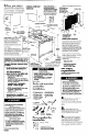
4
n
Line up the
“TOP” mounting
hole on anti-tip
bracket with mark
on wall. Use a pencil
to mark the location
of the top and
bottom mounting holes. Remove bracket.
If wall covering is ceramic tile, drill a 3/ 16-
inch hole through tile only. Then proceed as
follows:
For wood or metal wall studs:
Drill 1 /&inch holes at each mounting hole
location through wall and into stud.
For concrete or concrete block wall:
Drill 3/l 6-inch holes (l -3/4-inch minimum
deep) at each mounting hole location. Tap
plastic anchors into mounting holes with
hammer.
5
n
Line up holes on
bracket with holes on
wall, making sure that
the ‘TOP” mounting
hole on bracket is lined
up with top hole in wall.
Securely fasten bracket
( _.
4
to wall using screws provided.
6
n
Plug range power supply cord into
grounded outlet. Carefully slide range into
position until range is approximately 2 inches
from rear wall. Remove shipping base,
cardboard or hardboard
from under range.
7
n
Push cable,
located on rear of range,
up and into the two hooks
on the anti-tip bracket.
Check that cable is secure in both hooks by
pulling cable towards range. If cable comes
out of hooks, reposition cable to insure that
cable fits securely in both anti-tip bracket
hooks. Slide range into final position.
8
n
If installing the range in a mobile
home, you MUST-secure the range to the
floor. Any method of securing the range is
adequate as long as it conforms to the
standards listed in the Mobile Home
installation instructions, Panel A.
9
n
Place rack in oven. Place level on
rack, first side to side; then front to back. If
range is not level, adjust the leveling legs up
or down until the range is level.
Note: Oven must be level for satisfactory
baking conditions.
Do Not make connection too tight. The
regulator is die cast. Overtightening may
crack the regulator, resulting in a gas leak
and possible fire or explosion.
All connections must be wrench-
tightened.
flexible connector
l/2” flare union adapter
pressure
regulator
valve
10
n
Assemble the flexible connector
from the gas supply pipe to the pressure
regulator, located in burner box, in this
order: shutoff valve, l/2” flare union
adapter, flexible connector, l/2” flare union
adapter. Seal all openings in floor or wall
wherever range is installed.
Panel B