
Range User Manual


17
w Push in and turn the
control knob to the “LITE” position
blue flame. To adjust the burner, remove the
control knob and turn the adjustment screw
in the center of the valve stem. Check the
adjustment by turning the control knob from
“HI” to “LO” several times. The burner is
properly adjusted when the low flame
remains steady and the burner does not go
out. Check each burner.
and then to the “LO” position.
The low flame should be a
minimum, steady, blue flame. To
adjust the burner, remove the control knob
and turn the adjustment screw in the center
of the valve stem. Check the adjustment by
turning the control knob from ‘HI” to “LO”
several times. The burner is properly
adjusted when the low flame remains steady
and the burner does not go out. Check
each burner.
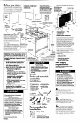
14. 17. 15a.
Numbers
correspond
to steps.
19a.
Make sure the
oven control
knob is in the
18
n
Remove oven rack. Remove
oven screws at rear of oven bottom. Pull
oven bottom rear up and remove front of
oven bottom from oven front. Remove oven
bottom. Remove baffle.
Check the operation of the oven burner.
Push in and turn
temperature control knob
to 300°F. The oven burner
should light in 50 - 60
seconds. This delay is
The oven safety valve requires
a certain time before it will open and allow
gas to flow.
“OFF” position. Remove the oven racks, oven
bottom, and oven burner baffle. Hold a
lighted match to the opening in the top of
the pilot at the rear of the oven burner. No
pilot adjustments are required.
n
Turn oven
thermostat knob to 300°F.
The oven pilot should now be
larger with the flame
extending down the slanted ramp
and burning against a small metal bulb.
After 20-40 seconds, the
main oven burner should
ignite and burn until the
oven temperature has
reached 300°F. At that
time, the oven pilot
should get smaller, moving away from the
metal bulb which will turn the main oven
burner off after 20-40 seconds.
The oven burner will continue to turn off and
on to maintain oven temperature.
2. 4.8.10.
11
n
Use pipe-ioint compound made
for use with Natural and L.P. gas to seal all
gas connections. If flexible connector is
used, be certain connector is not kinked.
12
n
Open the shutoff valve in the
Product Damage
. Do Not insert any object into the
openings of the protective shield that
surrounds the ignitor.
l
Do Not clean the area.
Failure to follow these instructions could
I
result in product damage.
I
19
w Check the oven
,ll’//~l1ll II,
gas supply line. Wait a few minutes for gas
to move through the gas line.
21a
n
Check the oven burner for
proper flame. This flame should be 1’ long,
with inner cone of bluish-green, and outer
mantle of dark blue and should be clean
and soft in character. No yellow tips,
blowing or lifting of flame should occur.
burner for proper flame. This flame
should have a 1 I long inner cone of
bluish-green, with an outer mantle
of dark blue, and should be clean
and soft in character. No yellow
tips, blowing or lifting of flame should occur.
Fire Hazard
Do Not use an open flame to test for leaks
from gas connections.
Checking for leaks with a flame may
result in a fire or explosion.
22a.
air
If oven flame needs to be
shutter
13
n
Use a brush and liquid detergent
20
n
If oven flame needs to
be adjusted, locate the air shutter
near the center rear of the oven
burner. Loosen screw and adjust
the air shutter until the proper
flame appears. Tighten screw.
21
n
Reolace the oven burner
baffle, oven bottom, and oven racks.
Standing Pilot System
14a
n
Be sure all control knobs are
in the “OFF” position. Remove grates and
raise the maintop.
to test all gas connections for leaks. Bubbles
around connections will indicate a leak. If a
leak appears, shut off gas valve controls
and adjust connections. Then check
connections again. NEVER TEST FOR GAS
LEAKS WITH A MATCH OR OTHER FLAME.
Clean all detergent solution from range.
Initial lighting and gas flame
adjustments depend on type of
system - electronic ignition or standing
pilot. Raise cooktop and check which system
is available. Continue installation, following
steps under the heading for this range’s
system.
Electronic Ignition System -
initial lighting and gas flame
adjustments.
Cooktop and oven burners use electronic
ignitors in place of standing pilots. When the
cooktop control knob is turned to ‘LITE”
position, the system creates a spark to light
the burner. This sparking continues until the
control knob is turned to the desired setting.
When the oven control is turned to the
desired setting, a glow bar heats up bright
orange and ignites the gas. No sparking
occurs and the glow bar remains on while
the burner operates.
adjusted, loosen screw and
adjust the air shutter until the
proper flame appears.
Tighten screw. Replace
burner baffle, oven bottom
and oven racks.
To get the most efficient use from your new
range, read your Use and Care Guide.
Keep Installation Instructions and Guide
close to the range for easy reference.
Gas conversion
The serial rating plate, located under the
maintop, specifies the type of gas this range
was set to use. Conversion should be done
by a qualified installer.
screw
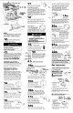
Natural to L.P. gas
Standing Pilot Models: CA,@< ~~%%
A
\!:‘:9&..; ‘<
n
Convert the pressure “;’ : ’ ‘-?, >\
‘7‘1
regulator. Do Not remove
-1
i\ ”
the pressure regulator.
_. .j
Al
.1 ’
small end towards
enlarged
regulator for
Q end
1. Remove the cap
from the pressure
regulator.
2. Remove the
plunger from the
cap.
3. Turn the plunger upside down with the
enlarged end down.
4. Replace the plunger inside the regulator.
5. Replace the cap.
Electric Ignition Models
A
n
Convert the pressure regulator. Do Not
remove the pressure regulator.
Adjust pilot adjusrment screw so pilot flame
tip is l/8” high and centered in the hole in the
pilot housing. If the flame is too high, carbon
(soot) will accumulate under the cooktop.
15a kTf%
n
Check the
14
n
Check the
operation of the cooktop
burners. Push in and turn
9
each control knob to “LITE”
position. The flame should light
w
,,0
within 4 seconds. Do Not leave the
knob in the “LITE” position after burner lights.
operation of the cooktop 02
burners. Push in and turn
each control knob to “LITE”
w
“O position. The flame should light
within 4 seconds. Do Not leave the knob in
the “LITE” position after burner lights.
16a
n
After burner liahts, turn
control knob to “HI” position. Check each
cooktop burner for proper flame. This small,
inner cone should have a very distinct blue
flame approximately l/2” long. The outer
cone is not as distinct as the inner cone.
15
l/2”
n
After burner lights,
-WI--
II $,.I II
turn control knob to ‘HI” position.
F=
Check each cooktop burner for
proper flame. The small inner cone
should have a very distinct blue
flame approximately l/2” long. The outer
cone is not as distinct as the inner cone.
I.
If burners need adjusting for
proper flame, adjust the air
hollow end
towards
solid end
regulator for
towards
natural gas
regulator for
1. Unscrew the
L.P. gas
16
n
If burners need
shutter to the widest opening
that will not cause the flame
to lift or blow off of the burner.
cap from the
pressure
regulator. Be sure
spring stays in place.
2. Turn the cap over
so the hollow end
faces outward.
3. Replace the cap of the regulator. The
letters L.P. should be visible on exposed
end of the cap.
adjusting for proper flame,
remove burner grates and
carefully lift up the
maintop. Adjust the air
air adjustment
shutter to the widest
opening that will produce a sharp blue flame
that does not lift or blow off of the burner.
Repeat as necessary with each burner.
Panel C
Repeat as necessary with each burner.
18a.
Push in and turn the control knob to the
“LITE” position and then to the “LO” position.
The low flame should be a minimum, steady,