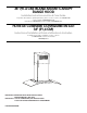
36" (91.4 CM) ISLAND-MOUNT CANOPY RANGE HOOD Installation Instructions and Use & Care Guide For questions about features, operation/performance, parts, accessories or service, call: 1-800-253-1301 or visit our website at www.whirlpool.com In Canada, call 1-800-807-6777 or visit our website at www.whirlpool.
TABLE OF CONTENTS TABLE DES MATIÈRES RANGE HOOD SAFETY .................................................................2 INSTALLATION REQUIREMENTS ................................................4 Tools and Parts ............................................................................4 Location Requirements................................................................4 Venting Requirements..................................................................5 Electrical Requirements ...................
IMPORTANT SAFETY INSTRUCTIONS WARNING: TO REDUCE THE RISK OF FIRE, ELECTRIC SHOCK, OR INJURY TO PERSONS, OBSERVE THE FOLLOWING: ■ Use this unit only in the manner intended by the manufacturer. If you have questions, contact the manufacturer. ■ Before servicing or cleaning the unit, switch power off at service panel and lock the service disconnecting means to prevent power from being switched on accidentally.
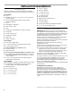
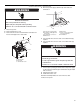
INSTALLATION REQUIREMENTS ■ T10 Torx®† adapter Tools and Parts ■ T20®† Torx® adapter Gather the required tools and parts before starting installation. Read and follow the instructions provided with any tools listed here. ■ 2 - Upper vent covers ■ 2 - Lower vent covers Tools needed ■ Level ■ 4 - Plastic vent clips ■ Drill with 1¼" (3.0 cm), ³⁄₈" (9.5 mm), ⁷⁄₆₄" (2.75 mm) and ¹⁄₈" (3.
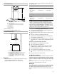
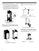
The chimneys can be adjusted for different ceiling heights. See the following chart. Product Dimensions A Vented Installations B C E A. 12¼" (31.1 cm) B. 13³⁄₁₆" (33.5 cm) C. *29³⁄₄" (75.6 cm) min. 44¹³⁄₁₆" (113.8 cm) max. **29³⁄₄" (75.6 cm) min. 49¹³⁄₁₆" (126.5 cm) max. D. 3¹⁄₂" (8.9 cm) E. 36" (91.4 cm) F. 25³⁄₁₆" (64.0 cm) *Vented installations only **Non-vented (recirculating) installations only Installation Dimensions B C Max. ceiling height Electric cooking surface 7' 8" (2.
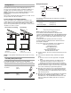
Example Vent System Venting Methods 90 elbow This island hood is factory set for venting through the roof. A 6" (15.2 cm) round vent system is needed for installation (not included). The hood exhaust opening is 6" (15.2 cm) round. NOTE: Flexible vent is not recommended. Flexible vent creates back pressure and air turbulence that greatly reduce performance. Vent system can terminate either through the roof or wall. To vent through a wall, a 90° elbow is needed. 2 ft (0.
INSTALLATION INSTRUCTIONS Prepare Location ■ Lay out the vent duct system before installing the range hood to determine the best routing for the vent duct. ■ It is recommended that the vent system be installed before the range hood is installed. ■ Before making cutouts, make sure there is proper clearance within the ceiling for exhaust vent. ■ Range hood is to be installed 24" (61.0 cm) min. for electric cooking surfaces, 27" (68.6 cm) min. for gas cooking surfaces, to a suggested maximum of 36" (91.
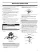
Assemble Range Hood 1. Install transition on top of hood (if removed for shipping) with 2 - 3.5 x 9.5 mm sheet metal screws. Install Range Hood Non-Vented (recirculating) Installation 1. Attach the air deflector to the upper horizontal support using 2 mounting screws. A B B B A A. Deflector B. Mounting screws A. Vent transition B. 3.5 x 9.5 mm screw (2) 2. Measure the length of 6" (15.2 cm) duct needed to connect the transition to the deflector. NOTE: Vent should fit up inside the deflector 1" (2.
Make Electrical Connection 4. Run home power supply cable through strain relief, into terminal box. WARNING A B Electrical Shock Hazard Disconnect power before servicing. C Replace all parts and panels before operating. F Failure to do so can result in death or electrical shock. 1. Disconnect power. 2. Remove terminal box cover. 3. Remove the knockout in the terminal box and install a UL listed or CSA approved ¹⁄₂" strain relief. E D G A. Home power supply cable B.
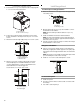
Install Duct Covers NOTE: Remove the film from the duct covers. 1. Assemble the upper duct covers together and install the duct covers around the support frame. The larger hole in the flanges of the upper duct cover must be outside the smaller hole in the mating flange of the other upper duct cover. 2. Secure the upper duct covers together with two 3.5 x 6.5 mm screws at the top and two 2.9 x 3 mm screws at the bottom. Install 1 screw on each side at the top and bottom of the assembled duct covers. 3.
6. Install the lower duct cover (rear) to the range hood canopy. Spread the lower duct cover opening slightly and position it over the upper duct cover. Set the lower duct cover in place. Position so the flanges of the lower duct cover set into the flanges of the upper duct cover. Make sure the front and rear lower duct covers mate properly.
RANGE HOOD USE The range hood is designed to remove smoke, cooking vapors and odors from the cooktop area. For best results, start the hood before cooking and allow it to operate several minutes after the cooking is complete to clear all smoke and odors from the kitchen. The hood controls are located on the front of the canopy. Range Hood Controls B A C D E A. On/Off light button B. Blower Off button C. Blower speed minimum button D. Blower speed medium button E.
RANGE HOOD CARE Cleaning IMPORTANT: Clean the hood and grease filters frequently according to the following instructions. Replace grease filters before operating hood. 4. Bend spring clips back into place to secure the charcoal filter to the metal filter. Exterior Surfaces: To avoid damage to the exterior surface, do not use steel wool or soap-filled scouring pads. Always wipe dry to avoid water marks.
G 2 RD YL/GN WH 1 N WH BK L L BR 3 BK L BU SWITCH OPERATION WH RD BK YL BR WH YL/GN FUNCTION Off No Connection Brown - Yellow (L - LA) Brown - White (L - 1) Brown- Red (L - 2) Brown - Black (L - 3) YL/GN WH RD BK N GY Low Speed YL Med Speed YL High Speed YL BR BU MOTOR CHARACTERISTICS YL M YL/GN BR YL WH RD GY BK BU YL 14 POSITION Lamps BK SE123C La YL WH Push Button Switch WIRING DIAGRAM Power Supply 120 VAC Frequency 60 Hz Power Absorption 2
ASSISTANCE OR SERVICE If you need service In Canada Please refer to the warranty page in this manual. If you need replacement parts If you need to order replacement parts, we recommend that you use only factory specified parts. Factory specified parts will fit right and work right because they are made with the same precision used to build every new appliance.
® WHIRLPOOL MAJOR APPLIANCE LIMITED WARRANTY ATTACH YOUR RECEIPT HERE. PROOF OF PURCHASE IS REQUIRED TO OBTAIN WARRANTY SERVICE. Please have the following information available when you call the Customer eXperience Center: ■ Name, address and telephone number ■ Model number and serial number ■ A clear, detailed description of the problem ■ Proof of purchase including dealer or retailer name and address IF YOU NEED SERVICE: 1.
SÉCURITÉ DE LA HOTTE DE CUISINIÈRE Votre sécurité et celle des autres est très importante. Nous donnons de nombreux messages de sécurité importants dans ce manuel et sur votre appareil ménager. Assurez-vous de toujours lire tous les messages de sécurité et de vous y conformer. Voici le symbole d’alerte de sécurité. Ce symbole d’alerte de sécurité vous signale les dangers potentiels de décès et de blessures graves à vous et à d’autres.
IMPORTANTES INSTRUCTIONS DE SÉCURITÉ AVERTISSEMENT : POUR RÉDUIRE LE RISQUE D'INCENDIE, CHOC ÉLECTRIQUE OU DOMMAGES CORPORELS, RESPECTER LES INSTRUCTIONS SUIVANTES : ■ Utiliser cet appareil uniquement dans les applications envisagées par le fabricant. Pour toute question, contacter le fabricant.
EXIGENCES D'INSTALLATION Outils et pièces Rassembler les outils et pièces nécessaires avant d’entreprendre l’installation. Lire et observer les instructions fournies avec chacun des outils de la liste ci-dessous.
Les cache-conduits peuvent être adaptés à différentes hauteurs de plafond. Voir le tableau suivant. Dimensions du produit A Installations avec décharge à l’extérieur B C Hauteur min. sous plafond Hauteur max. sous plafond Surface de cuisson électrique 7' 8" (2,34 m) 9' 10" (3,0 m) Surface de cuisson au gaz 7'11" (2,41 m) 9' 10" (3,0 m) Installations sans décharge à l’extérieur (recyclage) D F E D. 3¹⁄₂" (8,9 cm) E. 36" (91,4 cm) F. 25³⁄₁₆" (64,0 cm) A. 12¼" (31,1 cm) B. 13³⁄₁₆" (33,5 cm) C.
Installations dans une région à climat froid Dans le circuit d'évacuation, on devrait installer un clapet antireflux additionnel pour minimiser le reflux d'air froid, ainsi qu'un élément d'isolation thermique pour minimiser le transfert de chaleur par conduction vers l'extérieur. Le clapet anti-reflux doit être placé du côté air froid par rapport à l'élément d'isolation thermique.
■ Si le domicile possède un câblage en aluminium, suivre la procédure ci-dessous : 1. Raccorder une section de câble en cuivre massif aux conducteurs en queue de cochon. 2. Connecter le câblage en aluminium à la section ajoutée de câblage en cuivre en utilisant des connecteurs et/ou des outils spécialement conçus et homologués UL pour fixer le cuivre à l’aluminium. Suivre la procédure recommandée par le fabricant de connecteurs électriques.
4. Fixer le support horizontal supérieur à l'aide des 4 vis à bois de 5 x 45 mm. REMARQUE : Les vis du support horizontal supérieur doivent être vissées dans une structure de soutien du plafond capable de soutenir une charge de 80 lb (36,6 kg). 4. Fixer un deuxième ensemble de supports verticaux (A) et régler la hauteur verticale (B). Voir “Dégagements pour l’installation” dans la section “Exigences d’emplacement” pour déterminer la dimension souhaitée pour la hauteur verticale “B”.
2. Installer 16 vis de 4,2 x 8 mm et les fixer. Raccordement du circuit d’évacuation 1. Installer le circuit d’évacuation. 2. Enfoncer le conduit sur la bouche d'évacuation. Utiliser des brides de conduit pour assurer l'étanchéité de toutes les connexions. 3. Utiliser un calfeutrant pour assurer l’étanchéité au niveau de chaque ouverture. A A. Vis de montage Raccordement électrique AVERTISSEMENT 4. Acheminer le cordon d’alimentation du domicile à travers le serre-câble, dans le boîtier de connexion.
Installation des cache-conduits REMARQUE : Enlever la pellicule des cache-conduits. 1. Assembler les parties supérieures des cache-conduits ensemble et installer les cache-conduits autour du cadre de support. Le trou le plus gros sur les rebords de la partie supérieure du cache-conduit doit se trouver à l'extérieur du trou le plus petit sur le rebord en contact de l'autre partie supérieure du cache-conduit. 2.
6. Installer la partie inférieure du cache-conduit (arrière) à l'auvent de la hotte de cuisinière. Écarter la partie inférieure du cache-conduit en l'ouvrant légèrement et la positionner sur la partie supérieure du cache-conduit. Mettre en place la partie inférieure du cache-conduit. Positionner de façon à ce que les rebords de la partie inférieure du cache-conduit se placent dans les rebords de la partie supérieure du cacheconduit.
UTILISATION DE LA HOTTE La hotte de cuisinière est conçue pour extraire fumée, vapeurs de cuisson et odeurs de la zone de la table de cuisson. Pour obtenir les meilleurs résultats, mettre le ventilateur de la hotte en marche avant d’entreprendre une cuisson, et laisser le ventilateur fonctionner pendant plusieurs minutes après l’achèvement d’une cuisson pour pouvoir évacuer de la cuisine toute trace d’odeur de cuisson ou de fumée. Les commandes de la hotte sont situées à l’avant de l'auvent.
ENTRETIEN DE LA HOTTE Nettoyage IMPORTANT : Nettoyer fréquemment la hotte et les filtres à graisse en suivant les instructions suivantes. Réinstaller les filtres à graisse avant de faire fonctionner la hotte. Surfaces externes : 3. Placer le filtre à charbon dans la partie supérieure du filtre métallique. 4. Replier les attaches à ressort pour les remettre en place afin de fixer le filtre à charbon au filtre métallique.
BU JA BL BL R N JA BL MAR JA/VE 1 L Commutateur du bouton-poussoir N 3 MAR L BL La R JA/VE BL N Ph1 Neu Terre 2 SCHÉMA DE CÂBLAGE Fonctionnement du commutateur Position Fonction Off (arrêt) JA/VE BL R N N GY N JA JA BU Caractéristiques de moteur Alimentation électrique 120 VAC MAR JA JA M JA/VE MAR JA BL R GRIS N BU JA SE123C Pas de connexion Marron - Jaune Lampes (L - LA) Marron - Blanc Vitesse basse (L - 1) Marron - Rouge Vitesse moyenne (L - 2) Marron - Noi
ASSISTANCE OU SERVICE Si vous avez besoin de service Pour plus d’assistance Consulter la page de garantie du présent manuel. Si vous avez besoin de plus d’assistance, vous pouvez soumettre par écrit toute question ou préoccupation à Whirlpool Canada à l’adresse suivante : Whirlpool Brand Home Appliances Centre pour l’eXpérience de la clientèle Whirlpool Canada 200 - 6750 Century Ave.
GARANTIE LIMITÉE DES GROS APPAREILS MÉNAGERS WHIRLPOOL® ATTACHEZ ICI VOTRE REÇU DE VENTE. UNE PREUVE D’ACHAT EST OBLIGATOIRE POUR OBTENIR L'APPLICATION DE LA GARANTIE.
W10526058F ©2014. All rights reserved. Used under license in Canada. Tous droits réservés. Utilisé sous licence au Canada.