Ultra Low Nox Gas Water Heater with the Flame Lock® Safety System WARNING: If the information in these instructions is not followed exactly, a fire or explosion may result causing property damage, personal injury or death. Installation Instructions and Use & Care Guide Do not store or use gasoline or other flammable vapors and liquids in the vicinity of this or any other appliance. WHAT TO DO IF YOU SMELL GAS • Do not try to light any appliance.
WATER HEATER SAFETY Your safety and the safety of others are very important. We have provided many important safety messages in this manual and on your appliance. Always read and obey all safety messages. This is the safety alert symbol. This symbol alerts you to potential hazards that can kill or hurt you and others. All safety messages will follow the safety alert symbol and either the word “DANGER” or “WARNING.
INSTALLING YOUR GAS WATER HEATER Important Information About This Water Heater This gas water heater was manufactured to voluntary safety standards to reduce the likelihood of a flammable vapor ignition incident. New technology used in meeting these standards makes this product more sensitive to installation errors or improper installation environments. Please review the Installation Checklist found at the end of the installation instructions section and make any required installation upgrades or changes.
WARNING FLAMMABLES Flammable Vapors FIRE AND EXPLOSION HAZARD Can result in serious injury or death Do not store or use gasoline or other flammable vapors and liquids in the vicinity of this or any other appliance. Storage of or use of gasoline or other flammable vapors or liquids in the vicinity of this or any other appliance can result in serious injury or death. Read and follow water heater warnings and instructions. heater.
IMPORTANT: The water heater should be located in an area where leakage of the tank or connections will not result in damage to the area adjacent to the water heater or to lower floors of the structure. Due to the normal corrosive action of the water, the tank will eventually leak after an extended period of time. Also any external plumbing leak, including those from improper installation, may cause early failure of the tank due to corrosion if not repaired.
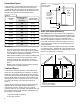
Gas Supply Figure 3 Gas Piping Manual Gas Shut-off Valve WARNING Ground Joint Union Check with local utility for minimum height 3” Minimum Explosion Hazard Use a new CSA approved gas supply line. Install a shut-off valve. Do not connect a natural gas water heater to an L.P. gas supply. Do not connect an L.P. gas water heater to a natural gas supply. Failure to follow these instructions can result in death, explosion, or carbon monoxide poisoning.
Combustion Air Supply and Ventilation WARNING Carbon Monoxide Hazard Water heater must be vented to outdoors. Vent must be installed by a qualified person using the installation instructions. Examples of a qualified person include: gas technicians, authorized gas company personnel, and authorized service persons. Combustion air must be free of acid-forming chemicals such as sulfur, fluorine, and chlorine.
Unconfined Space A water heater in an unconfined space uses indoor air for combustion and requires at least 50 cubic feet for each 1,000 BTU/HR of the total input for all gas appliances. The table below shows a few examples of the minimum square footage (area) required for various BTU/HR inputs.
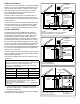
All Air from Outdoors Outdoor fresh air can be provided to a confined area either directly or by the use of vertical and horizontal ducts. The fresh air can be taken from the outdoors or from crawl or attic spaces that freely communicate with the outdoors. Attic or crawl spaces cannot be closed and must be properly ventilated to the outside. Ductwork must be of the same cross-sectional area as the free area of the opening to which they connect.
Figure 9 Draft hood Installation Alternative Opening Location Sheet Metal Screws (four provided) Draft hood Legs Confined Space 1 sq. Inch Per 3000 BTU/HR Legs Slot Jacket top Slot Install the draft hood with the four screws provided. Vent Pipe Size Figure 8B All Air from Outdoors Using a Single Permanent Opening It is important that you follow the guidelines in these instructions for sizing a vent pipe system.
Chimney Connection Listed Lined Chimney IMPORTANT: Before connecting a vent to a chimney, make sure the chimney passageway is clear and free of obstructions. The chimney must be cleaned if previously used for venting solid fuel appliances or fireplaces. Also consult local and state codes for proper chimney sizing and application or, in the absence of local and state codes, the “National Fuel Gas Code”, ANSI Z223.1(NFPA 54)-current edition.
Water System Piping Piping Installation Piping, fittings, and valves should be installed according to the installation drawing (Figure 13). If the indoor installation area is subject to freezing temperatures, the water piping must be protected by insulation. The water supply pressure should not exceed 80 psi. If this occurs, a pressure reducing valve with a bypass should be installed in the cold water inlet line.
Please note the following: • The system should be installed only with piping that is suitable for potable (drinkable) water such as copper, CPVC, or polybutylene. This water heater must not be installed using iron piping or PVC water piping. • Use only pumps, valves, or fittings that are compatible with potable water. • Use only full flow ball or gate valves. The use of valves that may cause excessive restriction to water flow is not recommended.
Temperature and Pressure Relief Valve WARNING Explosion Hazard If the temperature and pressure relief valve is dripping or leaking, have a qualified person replace it. Examples of a qualified person include: licensed plumbers, authorized gas company personnel, and authorized service personnel. IMPORTANT: Only a new temperature and pressure relief valve should be used with your water heater.
• should be vertical past any mixing valve or supply line to the air handler to remove air bubbles from the system. Otherwise, these bubbles will be trapped in the air handler heat exchanger coil, reducing the efficiency. instructions on the proper installation and operation of this water heater. Do not connect the water heater to any system or components previously used with non-potable water heating appliances when used to supply potable water.
Important Information About This Water Heater This gas water heater was manufactured to voluntary safety standards to reduce the likelihood of a flammable vapor ignition incident. The new technology used in meeting these standards makes this product more sensitive to installation errors. Please review the following checklist and make any required installation upgrades or changes. Questions? Call 1-877-817-6750.
OPERATING YOUR WATER HEATER Lighting Instructions Read and understand these directions thoroughly before attempting to light or re-light the pilot. Make sure that the view port (sight glass) is not missing or damaged. See Figure 23. Make sure the tank is completely filled with water before lighting the pilot. Check the data plate near the gas control valve/thermostat for the correct gas. Do not use this water heater with any gas other than the one listed on the data plate.
DANGER Water temperature over 125ºF can cause severe burns instantly or death from scalds. Children, disabled and elderly are at highest risk of being scalded. See instruction manual before setting temperature at water heater. HOT Feel water before bathing or showering. Temperature limiting valves are available, see manual.
Checking the Draft Burner Flames WARNING Burn Hazard Do not touch vent. Doing so can result in burns. After successfully lighting the water heater, allow the unit to operate for 15 minutes and check the draft hood relief opening for proper draft. Make sure all other appliances in the area are operating and all doors are closed when performing the draft test. Pass a match Figure 17 Draft Hood flame around the relief opening of the Relief Opening draft hood.
Water Temperature Regulation WARNING Water temperature over 125°F can cause severe burns instantly or death from scalds. Children, disabled and elderly are at highest risk of being scalded. Feel water before bathing or showering. Temperature limiting valves are available. The thermostat is adjusted to the pilot position when it is shipped from the factory. Water temperature can be regulated by moving the temperature dial to the preferred setting. The preferred starting point is 120°F at the “HOT” setting.
Operating the Temperature Control System Figure 19B: Status Codes List of status codes are shown at top of gas control valve/thermostat. Status Light Codes Normal Flashes: • 0 Flashes Indicates Control Off/Pilot Out. • 1 Flash Indicates Normal Operation. • Continuous Light indicates the gas control valve/thermostat is shutting down. Diagnostic Flashes: If the water heater is not working, look for the following diagnostic flashes after lighting the pilot.
Operational Conditions Condensation Moisture from the products of combustion condenses on the tank surface and the outside jacket of the water heater and forms drops of water which may fall onto the burner or other hot surfaces. This will produce a “sizzling” or “frying” noise. NOTE: This condensation is normal and should not be confused with a leaking tank. Condensation may increase or decrease at different times of the year.
MAINTENANCE OF YOUR WATER HEATER Draining and Flushing It is recommended that the tank be drained and flushed every 6 months to remove sediment which may build up during operation. The water heater should be drained if being shut down during freezing temperatures. To drain the tank, perform the following steps: Temperature and Pressure Relief Valve WARNING 1. Turn off the gas to the water heater at the manual gas shut-off valve. 2. Open a nearby hot water faucet until the water is no longer hot. 3.
Replacement Parts Natural Gas Burner (Ultra Low Nox) IMPORTANT: The following maintenance procedures are for the Flame Lock® Safety System components and should be performed by a qualified person. Check the burner to see if it is dirty or clogged. The burner may be cleaned with soft paint brush (Figure 24). Do not use a wire brush or any tool that may damage the burner screen. Important: Do not use the burner if the burner screen is damaged. NOTE: Damage may be rips or holes in the burner screen.
Replacing the Pilot/Thermopile Assembly External Inspection & Cleaning of the 1. Remove the burner assembly as directed previously. Flame-trap 2. Lift the retainer clip straight up from the back of the manifold component block (using a flat-blade screwdriver), then remove the manifold component block from the burner door assembly (Figure 25).
Replacing the Burner Door Assembly WARNING Figure 28 Combustion Chamber Flame-trap Bracket Explosion Hazard Tighten both burner door screws securely. Remove any fiberglass between gasket and combustion chamber. Replace viewport if glass is missing or damaged. Replace manifold component block if missing or removed. Door Gasket Piezoelectric Igniter System The piezoelectric igniter system consists of the igniter button, electrode, and wire.
Removing and Replacing the Gas Control Valve/Thermostat Removing the Gas Control Valve/Thermostat: 1. Turn the gas control/temperature knob to the “OFF” position (Figure 19A). 2. Turn off the gas at the manual shut-off valve on the gas supply pipe (Figure 3). 3. Drain the water heater. Refer to the section on “Draining and Flushing” and follow the procedure. 4. Disconnect the igniter wire from the igniter lead wire.
PROBLEM PILOT WILL NOT LIGHT OR REMAIN LIT (continued) POSSIBLE CAUSE(S) 13. Flammable vapors incident, Flame Lock® function utilized Replace gas control valve/thermostat Clean, locate source and correct Replace thermopile See maintenance section for inspection and cleaning of flame trap 13. Replace water heater, eliminate flammable vapors source. Call 1-877-817-6750. 1. 2. 3. 4. 5. 6. 7. 8. 9.
STATUS LIGHT CODE TROUBLESHOOTING CHART LED STATUS 0 FLASHES (LED NOT LIT) PROBLEM CORRECTIVE ACTION Pilot light is not lit. Not enough power (millivolts) to keep it lit. Follow the lighting instructions on the front of the water heater and record any diagnostic codes. See “Status Light Codes” section. 1 FLASH (EVERY 3 SECONDS) Normal operation. No corrective action necessary. 2 FLASHES Insufficient power (millivolts) to the 1. gas control valve/thermostat. 2. Check all wiring connections.
PILOT LIGHT TROUBLESHOOTING CHART Section A: Pilot light will not light (new installation). Is the manual gas shut-off valve, located in the supply line to the water heater, in the on position? YES Have you bled all the air from the pilot tube and gas supply line? YES NO While repeatedly depressing the igniter button, push in and hold the gas control/ temperature knob until the pilot is lit and maintains a stable flame, (status light will blink) then release the gas control/ temperature knob.
REPAIR PARTS ILLUSTRATION 1 6 5 7 4 When ordering repair parts always give the following information: 1. 2. 3. 4. Model, serial, and product number Type of gas Item number Parts description 8 Repair Parts List Item No.
Listed Parts Kits and Illustrations Item 11: Pilot assembly kit, which contains the pilot, electrode, and thermopile (Natural Gas) Item 12: Burner Door assembly, which contains the burner, gasket, door, pilot tube, manifold component block with retainer clip, temperature sensor, and pilot assembly.
NOTES 33
NOTES 34
NOTES 35
®/TM © 2015 Whirlpool. All rights reserved. Manufactured under license by American Water Heater Company, Tennessee. LOWE’S is a registered trademark of LF, LLC. Limited Warranty provided by Manufacturer.