
Installation Instruction


W10367612A - 3 -
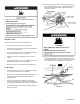
FIGURE 5 - STYLE “B’
NOTE: IF YOUR GAS DRYER HAS STYLE “A” FOLLOW
STEPS 15 TO 17. FOR STYLE “B” FOLLOW STEPS 18 TO 21.
STYLE A GAS VALVE CONVERSION
15. Remove the regulator vent cap (leak limiting device) from
the pressure regulator. See Figure 4.
16. Install the new blocking pin finger-tight. Do not tighten
more than 1/8 turn to seal it. See Figure 4.
17. Apply English or French conversion decal on top of the
burner data decal located on the burner baseplate.
NOTE: Proceed to next section ‘Installation Checklist’
STYLE B GAS VALVE CONVERSION
18. Observe the cover dial settings indicated as NG (Natural
gas) and LPG (Liquefied Propane gas) along with the gas
type indicator. See Figure 5.
FIGURE 6
19. Position a pair of bend pliers into the slots of the cover dial.
See Figure 6.
FIGURE 6
20. Rotate cover dial 25 degrees counter clockwise lining up
“LPG” marking with the indicator on the gas valve.
See Figure 7.
FIGURE 7
21 Apply English or French conversion label on top of the
burner data decal located on the burner baseplate.
NOTE: The blocking pin included with this kit is NOT used
with Style “B” gas valve.
Installation Checklist
Check that both labels have been installed as described in
steps 3, 17 or 21
If converting to Propane, check that the number 54 is not
marked on either of the remaining orifices. If converting to
Butane, check that the number 55 is not marked on either
of the remaining orifices.
Check that the regulator vent cap has been replaced by
the blocking pin as in Figure 4. (Style “A’ application only)