
Installation guide

improper venting can cause moisture and lint to collect
indoors, which may result in:
[] Moisture damage to woodwork, furniture, paint, wallpaper,
carpets, etc.
[] Housecleaning problems and health problems.
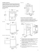
PLAN VENT SYSTEM
The design of the flue system should ensure that any condensate
formed when operating the appliance from cold, is either retained
and subsequently evaporated or discharged. Following these
installation instructions should adequately meet this requirement.
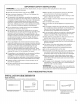
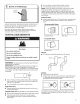
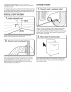
Recommended exhaust installations
Typical installations vent the dryer from the rear of the dryer.
Other installations are possible.
A. Dryer
B. Elbow
C. Wall
D. Exhaust hood
A--
B
G
E. Clamps
E Rigid metal or flexible metal vent
G. Vent length necessary to connect elbows
H. Exhaust outlet
Alternate installations for close clearances
Venting systems come in many varieties. Select the type best
for your installation. Two close-clearance installations are shown.
Refer to the manufacturer's instructions.
Over-The-Top installation (also available with one offset elbow)
Periscope installation
If you prefer, dryer may be converted to exhaust out right side,
left side, or through bottom. You must contact your local dealer
to have dryer converted.
Determine vent path:
[] Select route that will provide straightest and most direct
path outdoors.
[] Plan installation to use fewest number of elbows and turns.
[] When using elbows or making turns, allow as much room
as possible.
[] Bend vent gradually to avoid kinking.
[] Use as few 90° turns as possible.
Fire Hazard
Use a heavy metal vent.
Do not use a plastic vent.
Do not use a metal foil vent.
Failure to follow these instructions can result in death
or fire.
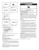
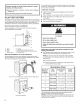
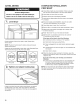
Determine vent length and elbows needed for best
drying performance:
[] Use following Vent System Chart to determine type of vent
material and hood combinations acceptable to use.
f
NOTE: Do not use vent runs longer than those specified
in Vent System Chart. Exhaust systems longer than those
specified will:
[] Shorten life of dryer.
[]
Reduce performance, resulting in longer drying times
and increased energy usage.
Number of
90 ° turns
or elbows
2
3
4
Vent System Chart
Type
of vent
Rigid metal
Rigid metal
Rigid metal
Rigid metal
Rigid metal
Box/Iouvered Angled
hoods hoods
15,8 m (52 ft.) 13,4 m (44 ft.)
13,4 m (44 ft.) 11,0 m (36 ft.)
11,0 m (36 ft.) 18,5 m (28 ft.)
8,2 m (27 ft.) 6,4 m (21 ft.)
6,1 m (20 ft.) 4,3 m (14 ft.
The Vent System Chart provides venting requirements that
will help achieve best drying performance.
NOTE: Side and bottom exhaust installations have a 90 ° turn
inside the dryer. To determine maximum exhaust length, add
one 90 ° turn to the chart.
8