
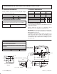
Specifications


3”
17-3/4”
16” R.
19”
38”
32”
64”
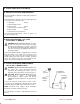
CUT-OUT DIAGRAM
DETAIL
1-1/2” I.P.S. THR’D.
1-1/2” O.D.
PUMP/CONTROL ACCESS
PUMP
42”
13-1/2”
6-1/2”
33-1/2”
67”
3-1/2”
2”
22”
2-7/8”
3”
3” FLAT
FAUCET
DECK
24” FLAT
FAUCET
DECK
FIELD WIRING
COMPARTMENT
4
113312-2-BA (9443)
Kohler Co., Kohler WI
1. ROUGHING-IN: K-1457-AA, K-1457-JA-AA, K-1457-J1-AA
A. ORDERING INFORMATION
Factory installed components include pump with integral
timer, and air switch transmitter.
Accessories/hardware:
Jet trim kit K-9698 required
Drain K-7161-AF recommended
B. REQUIRED ELECTRICAL SERVICE
Dedicated circuits required, protected with Class A
Ground-Fault Circuit-Interrupter (60 Hz) or ELCB (50
Hz):
Pump/control 120 V., 15 A, 60 Hz
or 230 V., 15 A, 50 Hz
C. PRODUCT INFORMATION
Fixture: basin area top area weight
Bathing well 50” x 29” 61” x 32” 120 lbs.
water depth capacity
To overflow 16” 100 gals.
Pump, 1-speed: low V Hz A
60 Hz 3/4 120 60 10
50 Hz 3/4 230 50 5.5
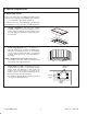
D. INSTALLATION NOTES
Refer to installation instructions included with fixture before
beginning installation.
Fixture should be on job site to determine cut-out
dimensions. Use 3/4” inward offset from bath rim.
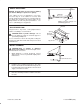
IMPORTANT: To ensure proper clearance and operation,
refer to faucet and drain manufacturer’s instructions
before drilling faucet holes.
If installing a rim-mount faucet, make sure there is no
interference with drain overflow and circulating system
before drilling any holes. Consult local and national codes
for minimum air gap requirements if installing a spout on
the faucet deck.
ROUGHING-IN NOTES
Fixture dimensions are nominal and conform to toler-
ances in ANSI Standard Z124.1.
No change in measurements if connected with drain
illustrated.
Minimum access:
Pump/control box 20” W x 15” H panel required