
Range User Manual

Electrical
requirements
(If model is so equipped.)
Eleclricol Shock Hozord
- Electrical ground k required on this
appllonce.
- Improper conneckon 01 the
equipment-grounding conductor
can result in tire, electrical shock,
or other personal injury.
- Check with o qualitied electrician it
You ore in doubt (II lo whether the
appliance is property grounded. Do
Not modity the power supply cord
plug. iT it will not fit the outlet. have
o proper outlet inslalled bY o
qualified electrician.
. Do Nol use an extension cord wilh
this applionca.
. Do Not have (1 fuse in the neutral or
grounding circtil. A fuse rn the
I-----’
neutral or grounding circuit could
result in on electrical shock:
Failure lo tallow lhese instructions
could result in fire, electrical shock
or olher personal Injuly.
A 1’2OVolt. &Hz. AC-only. 15.Ampere
haed electrical supply ls required
(Hmedeloy tise or &cult breaker Ls
recommended). It Is recommended that
a separate Clrcult serving only Hlls
appliance be ptovlded,
Electronic !gnit!an systems operate tithln
wide voltage Ilmlts. but proper arodina
and pokxiti are necesury: h addition G
checking that the oultet provktes 12Dvdt
power and k correcIiy grounded, the
otiet must be checked by a qwlit?ed
electrkian to zee II It Ir, correcny wired.
A tiring diagram b Included in literature
pcckage. The wiring diagram Is alsa
located on the back of the range.
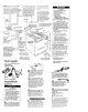
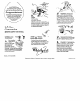
Recommended
grounding method
DO NOT. UNDER ANY CIRCUMSTANCES.
REMOVE THE POWER SUPPLY CORD
GROUNDING PRONG.
For Your personal safety. mls appliance
must be grounded. MS appliance Is
eaukwed with a power X&Y cord
h&l& a 3pro~~grwndlng plug. To
mlnlrrdze possible shock hazard. tlw cord
nx6t be plugged Into a mating J-prong
groundln@ype wall receptacle,
grcwded In accordawe m the
NaHanal Electrical Code. ANSI/NFPA 70 -
latest edltlcn”. and all local codes and
ordlnonces. (See Flgws 1.) n a maw
wall receptacle knot cwaUaMe. It Is the
electrklon.
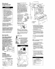
Alternate
grounding method
Do NOT. UNDER ANY CIRCUMSTANCES.
REMOVE THE POWER SUPPLY CORD
GROUNDING PRONG.
Electrical ground is required on this
oppllance.
II changing and properly grounding the
wall receptacle ir impossible and where
local codes permit (consult Your
5.
electrkal inspector). a tempotory
adaptor may be plugged Into the
extstlng 2.prong wall receptacle to mate
tim me
J-prong power y~p@Y cord.
If
mls
is done.You must connect a
saporate copper grounding tire (No.-18
mlnlmum) to a grounded cold water
pipe”’ by rneanr of a clamp and Men
to
me
external grounding connector
screw. Do not ground to a gas supply
pipe or hot water plpe. Do not connect
to electrtcal supply unti appliance is
permonentty grounded.
(see Film 2.)
- . I/..
. ..Gro”“ded cola water ptpe
must have metcl conti”“ltV
to electrlcoi ground and no,
be lnterrup+ed by ploshc.
rubber or other elec+ricoI
I~lanng Connectorssuch
OS hoser. hhrngs. Washers or
gaskets (inciudlng water
meter or pump). Any
electrIcal lnsularlng
cmnector should be
jumped 08 show- with
No.d wire securelv
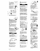
Now start...
With range in kitchen.
1 R
emove racks and oltwr parts
. fromltideoven.
to tree rear legs. Gently lower range to
floor. Tilt range backwards until front legs
are free
3
Remove shipplng materials. tape
. and protective film horn range.
Do not remove cardboard shipping base
at mis hme.
The backguard may already
be assembled to the range.
g If it Is not. Insert backguard
supports Into holder on the
sides 01 the range. Press
backguard down unltl locked
Into place.
Lin
cooMop and
insert backguard electikal
connector plug Into
receptacle In rtght rear 01
burner box area
Check that wtrlng Is not klnked of plnched
between holders and bockguard.
. To prevent tipping. tnstall range
anti-tip bracket.
- Sow these Instollalion Inslructions.
II range is moved to a new location.
the or&tip brackel must be
removed and reinslalled in the
new localion
anti-tip bracket must be installed Anti-hp
bracket may be fastened to the floor
under range or wall behmd range
16.
4.
Numbers
correspond
to steps.
To install anti-tip bracket on wall:
l
Measure and mark a line at the center
ol i% cabinet opening on the rear wall.
Measure and mark lines 12.13/16’ and
13.15116’ tram either the left or right side
of me center line on the rear wall.
Measure and mark on Ihe rear wall a line
3/B’ from the tloor
lo Instoll anti-tlp bracket on 11-r:
a Measure and mark a line at me Center
ol the cabinet opening on the Hoor.
Measure and mark lines 12-13/16’ar?d
13.15/16’ from either the lett or rtght side
of me center line on the Roar. Measue
arc mark on me floor a line I’ from the
rear wall.
Note: II ttwe Is a cabinet on only one side.
the anti-tip bracket must be Installed rw?.i
to the cabinet, using measurements gtven.
Go to Step 7.
II Hw range will Not be Installed
. agolnst a cabinet. the ant+tip
bracket must be Installed.
. Slide range Into final locahon. Mark a
lhne on the Rooi along each side of
range about onehalf me distance from
me rear to the Iront.
To Install anti-ttp brackel on wall:
l
Measure arc mark a lane on H-6 rear
wall at the center of
mhe ran33
location.
Measure and mark lines 12-113/l& and
13.15/16’ horn the lett or right sides of
me center line on the rear wall. Measure
and mark on the rear wall a line 310’ horn
me floor.
lo Install antl-tip brackel on Iloor:
. Measure and mark o lane on the noor at
the center of the range locatIon.
Meowreond morkllnes 12.13116’ond
13.15/16’ from the left or rlght’slde of
the center line on me floor. Measure
and mark on the floor a line 1’ horn ti
rear wall.
Go to Step 7.
Floor Damage
- Conloct o qualified carpet installer
tor the best procedure to drill
mounling holes through your type
01 carpet.
- Betore moving range across rIoor.
slide range onto cordbxxd or
hordboard.
Fo~lure lo totlow lhese instructions
may result in damage to tloor
CoverIng.
Panel B