Operating Instructions HOB Contents GB English, 1 RS , 11 Installation, 2-5 Positioning Electrical connection Gas connection Data plate Burner and nozzle specifications Description of the appliance, 6 Overall view Start-up and use, 7 Practical advice on using the burners Precautions and tips, 8 General safety Disposal CISTD 640 S /HA CISTD 640 S IX/HA 7HTD 640 S IX /HA 7HTD 640 IX/HA 7HTD 640 S /HA 7HTD 640 /HA 7HTD 641 S IX/HA Maintenance and care, 9 Switching the appliance off Cleaning the a
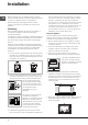
Installation ! Before operating your new appliance please read this instruction booklet carefully. It contains important information for safe use, installation and care of the appliance. also be equipped with vents to allow gas to escape in the event of a leak. As a result LPG cylinders, whether partially or completely full, must not be installed or stored in rooms or storage areas that are below ground level (cellars, etc.).
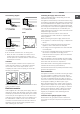
Hook fastening diagram Connecting the supply cable to the mains Hooking position for top H=20 mm Hooking position for top H=30 mm Front Install a standardised plug corresponding to the load indicated on the data plate. The appliance must be directly connected to the mains using an omnipolar circuit-breaker with a minimum contact opening of 3 mm installed between the appliance and the mains.
GB There is an adjustable L-shaped pipe fitting on the appliance supply ramp and this is fitted with a seal in order to prevent leaks. The seal must always be replaced after rotating the pipe fitting (seal provided with appliance). The gas supply pipe fitting is a threaded 1/2 gas cylindrical male attachment. Connecting a flexible jointless stainless steel pipe to a threaded attachment The gas supply pipe fitting is a threaded 1/2 gas cylindrical male attachment.
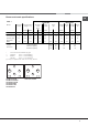
Burner and nozzle specifications GB Table 1 Liquid Gas Burner Diameter Thermal power (mm) kW (p.c.s.*) Nomin. Ridot. By-Pass 1/100 (mm) Natural Gas Nozzle 1/100 Flow* g/h Nozzle 1/100 (1) (mm) *** ** (mm) Flow* l/h Nozzle 1/100 Flow* l/h (mm) Fast (R) 100 3,00 0,70 41 39 86 218 214 116 286 143 286 Semi Fast (S) 75 1,65 0.
Description of the appliance GB Overall view Support Grid for COOKWARE GAS BURNERS Control Knobs for GAS BURNERS SAFETY DEVICES * Ignition for GAS BURNERS * • GAS BURNERS differ in size and power. Use the diameter of the cookware to choose the most appropriate burner to cook with. • Control Knobs for GAS BURNERS adjust the power or the size of the flame. • GAS BURNER ignition* enables a specific burner to be lit automatically.
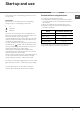
Start-up and use ! The position of the corresponding gas burner is shown on every knob. Gas burners Each burner can be adjusted to one of the following settings using the corresponding control knob: • Off Maximum Minimum To turn on one of the burners, place a lighted match or lighter near the burner, press the knob all the way in and turn it anti-clockwise to the "High" setting.
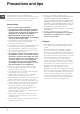
Precautions and tips GB ! This appliance has been designed and manufactured in compliance with international safety standards. The following warnings are provided for safety reasons and must be read carefully. General safety • This is a class 3 built-in appliance. • Gas appliances require regular air exchange to maintain efficient operation. When installing the hob, follow the instructions provided in the paragraph on “Positioning” the appliance.
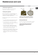
Maintenance and care Switching the appliance off GB Disconnect your appliance from the electricity supply before carrying out any work on it. Cleaning the appliance ! Do not use abrasive or corrosive detergents such as stain removers, anti-rust products, powder detergents or sponges with abrasive surfaces: these may scratch the surface beyond repair. ! Never use steam cleaners or pressure cleaners on the appliance.
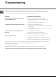
Troubleshooting GB It may happen that the appliance does not function properly or at all. Before calling the service centre for assistance, check if anything can be done. First, check to see that there are no interruptions in the gas and electrical supplies, and, in particular, that the gas valves for the mains are open. Problem Possible causes/Solution The burner does not light or the flame is not even around the burner. • The gas holes on the burner are clogged.
RS CISTD 640 S /HA CISTD 640 S IX/HA 7HTD 640 S IX /HA 7HT
! ! !
RS ! !
Таблица 1 Конфорка Диаметр (мм) Большая (R) Средняя (S) Малая (А) Mini WOK (MW) Давление подачи 100 75 55 110 Теплотворная способность кВт (p.c.s.
RS Опорные решетки для КАСТРЮЛЬ ГАЗОВЫЕ КОНФОРКИ Рукоятки-регуляторы ГАЗОВЫХ КОНФОРОК ЗАЩИТНОЕ УСТРОЙСТВО* Свеча зажигания ГАЗОВЫХ ГОРЕЛОК*
!
RS !
RS ! !
RS 05/2010 - 195061787.