® ® ELECTRONIC ELECTRIC DRYER Use & Care Guide For questions about features, operation/performance, parts accessories or service call: 1-800-253-1301 or visit our website at... www.whirlpool.com Table of Contents ................................................
TABLE OF CONTENTS DRYER SAFETY..............................................................................3 INSTALLATION INSTRUCTIONS ..................................................4 Tools and Parts ............................................................................4 Options .........................................................................................4 Location Requirements ...............................................................5 Electrical Requirements ....................
DRYER SAFETY Your safety and the safety of others are very important. We have provided many important safety messages in this manual and on your appliance. Always read and obey all safety messages. This is the safety alert symbol. This symbol alerts you to potential hazards that can kill or hurt you and others. All safety messages will follow the safety alert symbol and either the word “DANGER” or “WARNING.
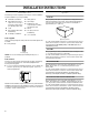
INSTALLATION INSTRUCTIONS Options Tools and Parts Check that you have everything necessary for correct installation. Proper installation is your responsibility. ■ Flat-blade screwdriver ■ Safety glasses ■ Adjustable wrench that opens to 1 in. (2.5 cm) or hex-head socket wrench (for adjusting dryer feet) ■ Vent clamps ■ Caulking gun and compound (for installing new exhaust vent) ■ Gloves ■ Tin snips (new vent installations) ■ ¼ in.
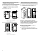
Installation clearances Location Requirements ■ The location must be large enough to fully open the dryer door. ■ Additional spacing should be considered for ease of installation and servicing. ■ Additional clearances might be required for wall, door and floor moldings. ■ Additional spacing of 1 in. (2.5 cm) on all sides of the dryer is recommended to reduce noise transfer. ■ Companion appliance spacing should also be considered.
Minimum installation spacing for recessed or closet installation, with or without a pedestal ■ The dimensions shown are for the minimum spacing allowed. ■ For closet installation, with a door, minimum ventilation openings in the top and bottom of the door are required. Louvered doors with equivalent ventilation openings are acceptable. Minimum installation spacing for cabinet installation ■ The dimensions shown are for the minimum spacing allowed.
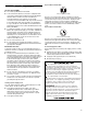
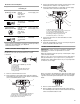
If your outlet looks like this: Electrical Requirements It is your responsibility ■ To contact a qualified electrical installer. ■ To be sure that the electrical connection is adequate and in conformance with the National Electrical Code, ANSI/NFPA 70-latest edition and all local codes and ordinances. The National Electric Code requires a 4-wire supply connection for homes built after 1996, dryer circuits involved in remodeling after 1996, and all mobile home installations.
Direct Wire Electrical Connection Power Supply Cord Fire Hazard Use 10 gauge solid copper wire. Fire Hazard Use a UL listed strain relief. Use a new UL listed 30 amp power supply cord. Disconnect power before making electrical connections. Use a UL listed strain relief. Connect neutral wire (white or center wire) to center terminal (silver). Disconnect power before making electrical connections. Connect neutral wire (white or center wire) to center terminal (silver).
Electrical Connection Options If your home has: And you will be connecting to: Go to Section 4-wire receptacle (NEMA Type 14-30R) A UL listed, 120/ 240 volt minimum, 30 amp, dryer power supply cord* 4-wire connection: Power supply cord A fused disconnect or circuit breaker box* 4-wire connection: Direct Wire A UL listed, 120/ 240 volt minimum, 30 amp.
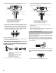
3. Connect ground wire (green or bare) of power supply cable to external ground conductor screw. Tighten screw. 4 1 2. Connect neutral wire (white or center wire) of power supply cord to the center, silver-colored terminal screw of the terminal block. Tighten screw. 1 3 2 4 2 5 3 6 5 1. External ground conductor screw 2. Green or bare copper wire of power supply cord 3. ³⁄₄ in. (1.9 cm) UL listed strain relief 4. Center silver-colored terminal block screw 5.
2. Place the hooked end of the neutral wire (white or center wire) of power supply cable under the center screw of terminal block (hook facing right). Squeeze hooked end together. Tighten screw. 6. Connect a separate copper ground wire from the external ground conductor screw to an adequate ground. 1 2 3 1 3 4 2 4 5 1. External ground conductor screw 2. Neutral grounding wire (green/yellow) 3. Center silver-colored terminal block screw 4. Neutral wire (white or center wire) 5. ³⁄₄ in. (1.
Use clamps to seal all joints. Exhaust vent must not be connected or secured with screws or other fastening devices which extend into the interior of the duct. Do not use duct tape. ■ Optional exhaust installations This dryer can be converted to exhaust out the right side, left side, or through the bottom. Contact your local dealer to have the dryer converted. IMPORTANT: Observe all governing codes and ordinances.
The angled hood style (shown following) is acceptable. NOTE: The following kits for close clearance alternate installations are available for purchase. Please see the “Assistance or Service” section of this manual to order. ■ Over the top Installation: 4" (10.2 cm) Part Number 4396028 ■ 2½" (6.4 cm) Periscope Installation (For use with dryer vent to wall vent mismatch): See the exhaust vent length chart that matches your hood type for the maximum vent lengths you can use. Part Number 4396037 - 0 in.
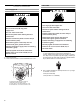
Install Leveling Legs WARNING Excessive Weight Hazard Use two or more people to move and install dryer. Failure to do so can result in back or other injury. 1. To protect the floor, use a large flat piece of cardboard from the dryer carton. Place cardboard under the entire back edge of the dryer. See illustration. 2. Firmly grasp the body of the dryer (not the console panel). Gently lay the dryer on the cardboard. 3. Examine the leveling legs. Find the diamond marking. 4.
DRYER USE Starting Your Dryer Explosion Hazard Keep flammable materials and vapors, such as gasoline, away from dryer. WARNING: To reduce the risk of fire, electric shock, or injury to persons, read the IMPORTANT SAFETY INSTRUCTIONS before operating this appliance. The following is a guide to starting your dryer. Please refer to specific sections of this manual for more detailed information. 1. Clean lint screen before or after each cycle. See “Cleaning the Lint Screen.” 2.
To use a Manual Cycle ■ Control Locked Rotate the dial to select a Manual Cycle. Press MORE TIME or LESS TIME until the desired drying time is displayed. Tap MORE TIME or LESS TIME and the time will change by 1-minute intervals. Press and hold MORE TIME or LESS TIME and the time will change by 5-minute intervals. The initial time displayed is the actual drying time. This feature allows you to lock your settings to prevent unintended use of the dryer.
Sensing Drying and Cycle Tips Select the correct cycle and dryness level or temperature for your load. If an Automatic Cycle is running, the display shows the estimated cycle time when your dryer is automatically sensing the dryness level of your load. If a Manual Cycle is running, the display shows the exact number of minutes remaining in the cycle. Cool Down tumbles the load without heat during the last few minutes of all cycles. Cool Down makes the loads easier to handle and reduces wrinkling.
Automatic Preset Cycle Settings Cycles Select the drying cycle that matches the type of load you are drying (see Automatic Preset or Manual Preset Cycle Settings charts). Cycle control knob Automatic Cycles Automatic Cycles allow you to match the cycle to the load you are drying. See the following “Automatic Preset Cycle Settings” chart. Each cycle dries certain fabrics at the recommended temperature. A sensor detects the moisture in the load and automatically adjusts the drying time for optimal drying.
End of Cycle Signal Additional Features The End of Cycle Signal produces an audible sound when the drying cycle is finished. Promptly removing clothes at the end of the cycle reduces wrinkling. WRINKLE SHIELD™ Feature When you are unable to remove a load of clothes from the dryer as soon as it stops, wrinkles can form. The WRINKLE SHIELD™ feature periodically tumbles, rearranges and fluffs the load to avoid wrinkles.
NOTE: Do not allow items to hang over the edge of the rack. DRYER CARE Cleaning the Dryer Location Keep dryer area clear and free from items that would obstruct the flow of combustion and ventilation air. 4. Close the door. 5. Select a timed drying cycle and temperature, or an air cycle (see following chart). Items containing foam, rubber, or plastic must be dried on a clothesline or by using the Air Only temperature setting. 6. You must select a time by pressing MORE TIME or LESS TIME.
As needed cleaning Laundry detergent and fabric softener residue can build up on the lint screen. This buildup can cause longer drying times for your clothes, or cause the dryer to stop before your load is completely dry. The screen is probably clogged if lint falls off while the screen is in the dryer. Clean the lint screen with a nylon brush every 6 months, or more frequently, if it becomes clogged due to a residue buildup. To wash 1. Roll lint off the screen with your fingers. 2.
TROUBLESHOOTING First try the solutions suggested here and possibly avoid the cost of a service call... Dryer displaying code message ■ ■ Dryer will not run ■ “PF” (power failure), check the following: Was the drying cycle interrupted by a power failure? Press (and hold) HOLD TO START button to restart the dryer. Has a fuse blown, or has a circuit breaker tripped? “E” Variable (E1, E2, E3) service codes: Call for service. Is the dryer door firmly closed? If not, the time display will blink.
Items shrinking ■ Was the dryer overloaded? Dry smaller loads that can tumble freely. ■ Did the load overdry? Check the manufacturer’s care label. Match dryer setting to load type. See “Cycles.” Loads are wrinkled ■ Was load removed from dryer at the end of the cycle? ■ Was dryer overloaded? Dry smaller loads that can tumble freely. ■ Did load overdry? Check the manufacturer’s care label. Match dryer setting to load type. See “Cycles.
WHIRLPOOL® DRYER WARRANTY ONE YEAR FULL WARRANTY For one year from the date of purchase, when this dryer is operated and maintained according to instructions attached to or furnished with the product, Whirlpool Corporation will pay for FSP® replacement parts and repair labor costs to correct defects in materials or workmanship. Service must be provided by a Whirlpool designated service company.