..<.q -i .I& : -z;xi’l.J’,r;.
H BEFORE YOU USE YOUR AIR CONDITIONER It is your responsibility to make sure that your air conditioner: Has been properly l Is the right to cool. l Copy your Model and Serial Numbers here... 1 . 2 . connected to electricity. l Is properly electrically grounded. Is properly used only intended to do. Is properly want for the job it was Is not used by children able to operate it properly. l or anyone not maintained. Also, remove energy label and buy guide.
Electrical Requirements For Your Air Conditioner ELECTRICAL REQUIREMENTS ARE DIFFERENT FOR THE TWO MODELS SHOWN ON THE COVER, DEPENDING ON THE AMPERE RATING OF YOUR UNIT. THE NUMBER OF AMPERES IS PRINTED ON THE SERIAL PLATE, ATTACHED TO THE FRONT OF THE UNIT, BEHIND THE FRONT PANEL (SEE PAGE 2). OBSERVE ALL LOCAL AND ORDINANCES GOVERNING Do not, under any circumstances, power supply cord ground prong.
INSTALLATION INSTRUCTIONS for Your Air Conditioner Unpack the mounting parts that came with your air conditioner window installation instruction you should follow. to determine which If you have these parts, follow: INSTRUCTION If you have these parts, follow: INSTRUCTION 1 (below). (on page 8): Installation Instructions 1 l , Unpack mounting parts before installing your air conditioner. Make sure you have all the necessary parts (see Figure 3).
2 l Pick the right window. First, decide what room(s) you want to cool. Then choose a window that will allow the air-conditioned air to flow freely and directly into the room(s) you want cooled. Remember, it’s difficult to move air around corners. If the inner sliding window slides to the left, the unit will be installed on the right. Remove window screen if there is one. Choose a sliding window that’s also near an electrical outlet.
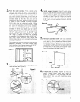
7 8 l l Install shelf 2-3/8” from opening (see Figure 9). side of window Measure height of opening (see Figure 9). Subtract 20-9116 ” from measured height. This will be the actual height of translucent panel 11 l Peel backing from seal strip (Item 8) and press it onto side filler frame guides on each side of unit (see Figure 12). Figure Figure 9 c 2-3/B” 9 l Measure out the distance from Figure 9 and mark it along the 20-l ‘4” side of translucent panei.
13 16 . Using l/8” drill, install locking screws (Item 7). Use two screws in top jamb and in the side bottom flanges (see Figure 14). If you need additional holding strength, add two more screws at upper sides of filler frame (marked “A”). Also, two screws can be added at unit sides (marked “B”). However, if you add screws at “B”, you must use a 3 ‘16” drill bit to predrill through the plastic sides of air conditioner l Figure 14 FOR INSTALLATION WINDOWS THAT DO OR TOP TRACK.
Figure 19 15-112” MIN. 1 IG 1 CENTER AVAILABLE 20 . + UNIT IN OPENING ROOM SIDE Drill g/64” holes in the window jamb top to line up with holes in filler frame (see Figure 19). Use two thread cutting screws (Item 13) to secure unit. If you need additional holding strength, add to screws at the bottom of the unit side channels (see Figure 14 on page 7). z Unpack mounting parts before installing your air conditioner. Be sure you have all the necessary parts (see Figure 20 and 21).
~’ -i i . them loose enough so there is about l/16” of play. Tighten the bottom screws (Item 2). This will pull the unit mounting flange tightly to the window frame, sealing and locking the air conditioner in place. Remove selected. the glass from the frame opening Clear away any hardened putty. Before sliding unit through the casement opening, remove the bottom window bracket (Item 3) on both sides of the unit. NOTE: only the top screws (Item 1) need to be removed. WIN[IOW 8 .
HOW TO START AND USE YOUR AIR CONDITIONER THERMOSTAT CONTROL FAN SPEED CONTROL EXHAUST CONTROL FAN SPEED CONTROL THERMOSTAT CONTROL Be sure air conditioner it in. To Start Your Air Conditioner 1 l 2 l is OFF before plugging The Exhaust Control The Exhaust Control setting smoky air from the room. Set exhaust control (if your unit is so equipped) to CLOSED for maximum cooling. Choose either speed setting. LO COOL or HI COOL fan LO COOL . . . . . . . . . . for sleeping comfort HI COOL . . . . .
2. To circulate room air Set exhaust control to CLOSED. control to FAN ONLY. Adjust fan Cleaning and Caring fdr Your Air Conditioner Proper use and care of your air conditioner will help insure longer life and lower operating costs. Follow these instructions carefully. Call your dealer for an annual checkup. Cleaning of Front Panel CLOSED FAN ONLY 1 Remove the front panel from unit when cleaning. Press down at top edge of the front as shown in Figure 30 or 31 (depending on your model).
. . ,.~._ ., II j ._ _ _: i Cleaning Air Conditioner Filter The filter is cleanable. A clean filter helps remove dust, lint and other particles from the air. Check every two weeks to see if filter needs cleaning. 1 Call the service company recommended by your dealer to: l Inspect and clean the coils and condensate water passages. Remove filter by releasing it from plastic clips as shown in Figure 32 or 33 (depending on your model). l 2 0 Clean filter, l Check fan and oil the fan motor.
Notes: Oiling of the Fan Motor 1 l Oil the fan motor per instructions on the motor. To add oil, pull out the oil hole plug at each end of the motor. (see Figure 34). OIL PLUGS An easy to use one-ounce capsule of especially recommended oil (Part No. 10943) can be ordered from your dealer. 2 3 . Replace the plug to keep dirt bearings. l from motor Reinstall the unit in cabinet after performing maintenance. (See Installation Instructions.
COOLING LOAD GUIDE-SQUARE FEET METHOD ROOM AIR CONDITIONERS To make sure you choose the right size umt. use this COOLING LOAD GUIDE SQUARE FEET It IS a quick. easy means of computing capacity METHOD For WIWIXS In e~praure shading lnsulallon and bulldlng construction AHAM Cooling Load Esllmate Form FtAC~l must be used 2000 I800 1600 I400 1200 1000 800 600 400 200 x z 8 z E c 8 a is = 8 E 8 s z RI g ; 8 z s R COOLING CAPACITY REQUIRED-BTU/HR INSTRUCTIONS: 1.
If you needserviceor assistance,we suggestyou follow thesefour steps: 1. Before calling for assistance 3. If you need service Whirlpool Performance problems often result from little things you can find and fix yourself without tools of any kind. Unit won’t run: 1. Is unit plugged in? 2. Is switch ON? 3. Is thermostat set too WARM? 4. Is time-delay fuse blown? 5. Has local Dower failed? Unit blows fuses: 1. Are time-delay fuses used? 2. Is an extension cord being used? (Do not use.) 3.
Part No. 203873/950491 !ifiers, Automatic Rev. A Washers, Clothes Dryers, Freezers, 0 1985 Whirlpool Refrigerator-Freezers, Corporation Ice Makers, Dishwashers, Built-In Printed in U.S.A.