INSTRUCTIONS AND ADVICE FOR INSTALLING, USING AND SERVICING OF COOKERS INSTRUCTIONS D’INSTALLATION, D’UTILISATION, ET D’ENTRETIEN DE LA CUISINIÈRE ENGLISH FRANÇAIS Instructions for use Page 3-28 Mode d’emploi Page 29-54
CONTENTS IMPORTANT SAFETY INSTRUCTIONS 4-7 DESCRIPTION OF THE APPLIANCE 8-9 USER’S INSTRUCTIONS 10-17 TROUBLESHOOTING 18 TECHNICAL FEATURES 19 INSTRUCTIONS FOR THE INSTALLER 20-27 AFTER-SALES SERVICE 28 3
IMPORTANT SAFETY INSTRUCTIONS This manual and the appliance itself provide important safety advices, to be read and observed at all times. All safety advices give specific details of the potential risk present and indicate how to reduce risk of injury, damage and electric shock resulting from improper use of the appliance. Carefully observe the following instructions: • The appliance must be disconnected from the power supply before carrying out any installation work.
IMPORTANT SAFETY INSTRUCTIONS inner parts, thoroughly check that the appliance is in perfect condition. If you have any doubts do not use the appliance and call in a qualified person. • The packaging materials used (cardboard, plastic bags, polystyrene foam, nails, etc.) must not be left with in easy reach of children because they are a potential hazard source. All packaging materials used are environmentallyfriendly and recyclable.
IMPORTANT SAFETY INSTRUCTIONS parts will become hot when in use. To avoid burns and scalds young children should be kept away. Young children should be supervised to ensure that they not play with the appliance.
IMPORTANT SAFETY INSTRUCTIONS environment and health, and also enables the materials making up the product to be recycled. For more detailed information on the available refuse collection systems, refer to the local Municipal Solid Waste disposal centre or the shop where the product was purchased. Producers and importers are responsible for fulfilling their obligations as regards recycling, treatment and environmentally friendly disposal by directly or indirectly participating in the collection system.
DESCRIPTION OF THE APPLIANCE PRESENTATION This cooker is fitted to a hob and an oven on gas. Each knob on the front panel has a diagram above and it is showing to which burner it refers. The combination of the different sized burners offers the possibility of various types of cooking. The oven walls are fitted with various runners (fig. 1) on which the following accessories can be placed. Supply and quantities vary from model to model (fig.
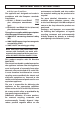
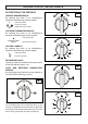
DESCRIPTION OF THE APPLIANCE DESCRIPTION OF THE CONTROLS A HOB GAS BURNER KNOB (A) By rotating the knob in an anticlockwise direction, the following symbols appear: 0 = Closed position = “Full on” position = “Reduced rate” position GAS OVEN THERMOSTAT KNOB (B) By rotating the knob in an anticlockwise direction, the following functions appear: = Closed position from Min.
USER’S INSTRUCTIONS HOB: GENERAL NOTES ON SAFETY LIGHTING THE BURNERS N.B. Burners are equipped with safety thermocouples and can only be ignited with the knob at the «Full on» position Once a burner has been lit, keep the knob pressed for about 10 seconds. When a gas cooker is being used it produces heat and humidity in the room where it is installed.
USER’S INSTRUCTIONS OVEN: GENERAL SAFETY INSTRUCTIONS IMPORTANT!! • Always keep the oven door closed during baking. • If the cooker is not fitted with the control knobs shield, the gas grilling operation MUST be done keeping CLOSE the oven door. • Do not leave the oven unsupervised during use. Ensure that children do not play with the appliance. • Always keep the appliance lid open when using the oven, in order to prevent overheating. • Always grip the centre of the oven door when opening.
USER’S INSTRUCTIONS HOW TO USE GAS OVEN AND GRILL 3. 4. 5. The oven and grill burner are be fitted with a safety thermocouple so, once the burner has been lit, keep the knob pressed for about 15 seconds. If, at the end of this time, the burner fails to light, release the knob and wait at least 1 minute before trying again. Should the burner turn out accidentally, turn the knob round to the closed position and wait at least 1 minute before lighting it again. 6. 7.
USER’S INSTRUCTIONS AUTOMATIC ELECTRICAL IGNITION OF GRILL BURNER HOW TO USE THE SPIT (fig. 7)(fig. 5) • Place the chicken or piece of meat to roast firmly between the two forks on the spit and make sure it is evenly balanced to prevent straining the motor. • Rest the spit on the support introducing the end in the seat and unscrew and remove the hand grip from the spit. • Fit support into the corresponding runner, and insert its end into the relative motor coupling.
USER’S INSTRUCTIONS USEFUL COOKING TIPS Meat: • If, when cooking meat, the time needed is more than 40 minutes, turn the oven off 10 minutes before the end of cooking time to exploit the residual heat (energy saving). • Your roast will be juicier if cooked in a closed pan; it will be crispier if cooked without a lid. • Normally white meat, poultry and fish need medium temperatures (less than 200°C). • To cook “rare” red meats, high temperatures (over 200°C) and short cooking times are needed.
USER’S INSTRUCTIONS FOODS CAKES Angel Cake Fruit Cake Almond Cake Chocolate Cake PASTRIES Biscuits in general Brioches Puff pastry Shortcrust pastry BAKED PASTE Lasagne Cannelloni PIZZA BREAD MEAT Roast beef Roast veal Roast lamb Roast pork GAME Roast hare Roast pheasant Roast partridge POULTRY Roast turkey Roast chicken Roast duck FISH Baked fish Casseroled fish Weight kg COOKING/BAKING TABLE Position of the oven Temperature shelf from the bottom in °C Cooking time in minutes 2 2 2 2 190 220 200 190
USER’S INSTRUCTIONS To maintain the shine of the enamelled parts, clean them with warm soapy water, rinse and dry them thoroughly. ALWAYS wash the accessories used. CLEANING AND MAINTENANCE To keep the surface of the hob and the various components in pristine condition (grill, enamelled covers, burner heads and flame diffusers, it is very important to wash them in warm soapy water, rinse and dry them well after each use.
USER’S INSTRUCTIONS 10 11 PL S L L P L C S OVEN SEAL D PL The oven seal guarantees the correct functioning of the oven. We recommend you: • clean it, avoiding abrasive tools or products. • check its state now and then. S 12 L If the oven door seal has become hard or is damaged, contact our Service Centre and avoid using the oven until it has been repaired.
TROUBLESHOOTING Some of the problems occur because of simple maintenance oversights or operation mistakes and can easily be resolved without having to call for technical assistance. PROBLEM The appliance is not working REMEDY • Make sure the gas cock is open • Check the plug is in • Check that the knobs are set correctly for cooking and then repeat the operations given in the handbook • Check the electrical system safety switches (RCD). If there is failure in the system call an electrician in.
TECHNICAL FEATURES BURNER DISPOSITION ON THE HOB BURNERS N. DENOMINATION 2 Rapid 3 Semi-rapide 4 Auxiliary 6 Ultrarapid central 7 Oven Grill with 8 separated control Operating Pressure Gas Rate Diameter Injectors Sabaf Heat Input W Air Reg.
INSTRUCTIONS FOR THE INSTALLER TECHNICAL INFORMATION INSTALLATION • The installation, adjustments, conversions and maintenance operations listed in this part must only be carried out by qualified personnel. The manufacturer cannot be held responsible for any damage to persons or property resulting from an incorrect installation of the appliance. • The safety and automatic adjustment devices of the appliances may, during its life, only be modified by the manufacturer or duly authorised supplier.
INSTRUCTIONS FOR THE INSTALLER VENTILATION The appliance should not be installed in a room of volume less than 20 m³. The quantity of air necessary is that required for a regular combustion of the gas and for the ventilation of the room. The natural flow of air must be direct through permanent openings in the walls of the room that open directly to the outside with a minimum cross section of 100 cm2 (fig. 14). These openings must be positioned so they cannot be obstructed.
INSTRUCTIONS FOR THE INSTALLER GAS CONNECTION SECURING THE COOKER TO WALL (fig. 19) Before connecting the appliance check that the data on the rating plate affixed to the cooker, correspond to those of the gas mains. A label on the back of this handbook and at the back of the cooker gives the appliance adjustment conditions, that is, the type of gas and operating pressure. Once the cooker is installed, check there are no leaks using a soapy solution (never a flame).
INSTRUCTIONS FOR THE INSTALLER The appliance’s gas inlet fitting is a threaded 1/2” male cylindrical type, in compliance with the UNI-ISO 228-1 standards. If gas is distributed through ducts the appliance must be connected to the gas mains with: • a rigid steel pipe, in accordance with standards, whose joints must be made using threaded fittings in accordance with the UNI-ISO 7/1 standard. The use of hemp with suitable adhesives or Teflon tape as a sealant is allowed.
INSTRUCTIONS FOR THE INSTALLER ADJUSTMENTS OVEN THERMOSTAT (fig. 21) Reduced rate adjustment should be carried out in the following way: • Remove the knob thermostat. • Switch on the oven burner by turning the relative knob to the Maximum position, then wait about 10 minutes. • Slowly turn the knob back to the Minimum position and, using a small screwdriver (C), turn screw (V) to the right to lower the flame or to the left to increase it. The flames must be short for an efficient Reduced rate setting.
INSTRUCTIONS FOR THE INSTALLER OVEN BURNER (fig. 22) The burner is installed on the oven base and is covered by the bottom plate which must always remain in that position during oven operation, To adjust the primary air, light the burner and, watching the flame, slacken screw (A) and adjust sleeve (B) to obtain the X openings indicated in the table paragraph Lock screw (A) in place once the adjustments have been made. C A 22 B D GRILL BURNER (fig.
INSTRUCTIONS FOR THE INSTALLER MAINTENANCE • Reassemble all the parts following the same procedure but in the reverse order. Prior to any maintenance work or changing parts, disconnect the appliance from the gas and electricity power sources. REPLACING THE TAPS AND THERMOSTAT Proceed in the following way when replacing a tap or the thermostat: • Remove pan supports, burner heads. • Unscrew the burner fixing screws (Vc) (fig. 25).
INSTRUCTIONS FOR THE INSTALLER ELECTRICAL CONNECTION CHANGING THE FLEXIBLE GAS HOSE In order to guarantee that the gas hose is always in excellent condition we strongly recommend changing it on the date you will find printed on it. The electrical connection must be carried out in accordance with the current standards and laws in force. Before connecting check that: • The system and electrical sockets amperage is adequate for the appliance maximum power (see data label affixed on the back of the cooker).
AFTER-SALES SERVICE Before calling the After-Sales Service: 1. See if you can eliminate the problem on your own (see “Troubleshooting Guide”). 2. Switch the appliance off and on again to see if the problem persists. If the fault persists after the above checks, contact your nearest After-Sales Service. Specify: • the type of fault; • exact type and model of oven; • the After-Sales Service number (the number given after the word “Service” on the dataplate) located inside the storage compartment flap.
TABLE DES MATIÈRES INSTRUCTIONS IMPORTANTES SUR LA SÉCURITÉ 30-33 DESCRIPTION DE L’APPAREIL 34-35 MODE D’EMPLOI 36-43 CHARTE DE DÉPANNAGE 44 CARACTÉRISTIQUES TECHNIQUES 45 INSTRUCTIONS À L’INTENTION DE L’INSTALLATEUR SERVICE APRÈS-VENTE 46-53 54 29
INSTRUCTIONS IMPORTANTES SUR LA SÉCURITÉ Des messages importants concernant la sécurité sont insérés dans le présent manuel et apposés sur l’appareil ; il convient de les lire et de les observer en toute circonstance. Tous les messages relatifs à la sécurité spécifient le danger potentiel auquel ils se réfèrent et indiquent comment réduire le risque de blessures, de dommages et de chocs électriques résultant d’une utilisation non réglementaire de l’appareil.
INSTRUCTIONS IMPORTANTES SUR LA SÉCURITÉ Nous vous remercions d’avoir choisi l’un de nos produits. Nous sommes certains que ce nouvel appareil, fonctionnel et pratique, fabriqué à partir de matériaux de toute première qualité, satisfera toutes vos exigences. Cet appareil est facile à utiliser, toutefois avant de l’installer et de l’utiliser, il est important que vous lisiez complètement le présent manuel avec la plus grande attention.
INSTRUCTIONS IMPORTANTES SUR LA SÉCURITÉ AVERTISSEMENT : L’appareil et ses parties accessibles deviennent chauds pendant l’utilisation. Veillez à ne pas entrer en contact avec les résistances de l’appareil. Les enfants de moins de 8 ans doivent être tenus à distance ou être surveillés en permanence. La vitre de la porte du four et les parties accessibles deviennent chaudes pendant l’utilisation du four.
INSTRUCTIONS IMPORTANTES SUR LA SÉCURITÉ Cet appareil est conforme aux dispositions de la Directive européenne 2002/96/CE. Le symbole de la poubelle barrée à roulettes figurant sur l’appareil indique que le produit arrivé au terme de sa vie utile doit être éliminé séparément des autres déchets. Par conséquent, il doit être remis à un centre de collecte spécialisé dans le recyclage des appareils électriques et électroniques, ou au revendeur lors de l’achat d’un appareil neuf équivalent.
DESCRIPTION DE L’APPAREIL PRÉSENTATION Cette cuisinière est équipée d’une table de cuisson et d’un four à gaz. Un diagramme est imprimé au-dessus de chaque bouton du bandeau de commande, indiquant à quel brûleur celui-ci correspond. Il est possible d’associer des brûleurs de dimensions différentes selon le type de cuisson souhaité. Les parois de la cavité du four sont dotées de plusieurs guides (fig. 1) sur lesquels vous pouvez placer les accessoires suivants.
DESCRIPTION DE L’APPAREIL DESCRIPTION DES COMMANDES A BOUTON DES BRÛLEURS À GAZ DE LA CUISINIÈRE (A) Si vous tournez le bouton dans le sens antihoraire, les symboles suivants s’affichent : 0 = Position « Fermé » = Position « Grande flamme » = Position « Petite flamme » BOUTON THERMOSTAT DU FOUR À GAZ (B) Lorsque vous tournez le bouton dans le sens antihoraire, les fonctions suivantes apparaissent: B = Position « Fermé » du Min. au Max.
MODE D’EMPLOI TABLE DE CUISSON : ECOMMANDATIONS GÉNÉRALES EN MATIÈRE DE SÉCURITÉ ALLUMAGE DES BRÛLEURS REMARQUE : les brûleurs sont équipés d’un thermocouple de sécurité et ne s’allument que lorsque le bouton est placé sur la position « grande flamme ». Dès que le brûleur est allumé, maintenez le bouton enfoncé pendant environ 10 secondes. L’utilisation d’une cuisinière gaz entraîne un dégagement de chaleur et d’humidité dans la pièce où l’appareil est installé.
MODE D’EMPLOI FOUR : CONSIGNES GÉNÉRALES DE SÉCURITÉ • Après avoir utilisé l’appareil, vérifiez que tous les boutons de commande sont placés sur la position d’arrêt. • AVERTISSEMENT !!! Pendant et après l’utilisation, la vitre de la porte du four et les parties accessibles de l’appareil peuvent être très chaudes. Par conséquent, veillez à ce que les enfants ne s’approchent pas de l’appareil. • Surveillez constamment le four lorsque vous l’utilisez.
MODE D’EMPLOI UTILISATION DU FOUR ET DU GRIL À GAZ 3. Fermez doucement la porte du four. 4. Attendez 10 minutes, puis ouvrez la porte du four. 5. Appuyez sur le bouton de commande du four, tournez-le dans le sens inverse des aiguilles d’une montre jusqu’à la position Maximum ; maintenez le bouton enfoncé pendant quelques secondes jusqu’à ce que la flamme soit stabilisée, puis fermez doucement la porte du four. 6. Réglez la température souhaitée à l’aide du bouton de commande du four. 7.
MODE D’EMPLOI ALLUMAGE ÉLECTRIQUE AUTOMATIQUE DU BRÛLEUR DU GRIL COMMENT UTILISER LE TOURNEBROCHE (ill. 5) • Placez le poulet ou le morceau de viande à rôtir entre les deux fourchettes du tournebroche. Assurez-vous que la pièce de viande est bien équilibrée sur le tournebroche, de façon à éviter des contraintes au niveau du moteur. • Posez le tournebroche sur le support en introduisant l’extrémité dans le logement prévu à cet effet ; dévissez et retirez la poignée du tournebroche.
MODE D’EMPLOI CONSEILS DE CUISSON UTILES Viande : • Lorsque vous cuisez de la viande, si le temps de cuisson dépasse 40 minutes, éteignez le four 10 minutes avant la fin de la cuisson pour utiliser la chaleur résiduelle (économie d’énergie). • Votre rôti sera plus juteux si vous le cuisez dans un récipient fermé ; il sera plus croustillant si vous le cuisez sans le couvrir. • En règle générale, la viande blanche, la volaille et le poisson requièrent une température de cuisson moyenne (inférieure à 200 °C).
MODE D’EMPLOI ALIMENTS GÂTEAUX Gâteau des anges Gâteau aux fruits Gâteau aux amandes Gâteau au chocolat VIENNOISERIES Biscuits en général Brioches Pâte feuilletée Pâte brisée PÂTES AU FOUR Lasagnes Cannelloni PIZZAS PAIN VIANDE Rosbif Rôti de veau Rôti d’agneau Rôti de porc GIBIER Lièvre rôti Faisan rôti Perdrix rôtie VOLAILLE Dinde rôtie Poulet rôti Canard rôti POISSON Poisson au four Casserole de poisson Poids kg TABLEAU DE CUISSON Position de la grille en partant du bas Température en °C Temps de cui
MODE D’EMPLOI NETTOYAGE ET ENTRETIEN qu’ils ne carbonisent, ne forment des dépôts et des taches indélébiles et ne dégagent des odeurs désagréables lorsque vous réutiliserez le four. Pour conserver le brillant des parties émaillées, nettoyez-les à l’aide d’une solution d’eau chaude savonneuse, rincez et séchez soigneusement. Veillez à TOUJOURS nettoyer les accessoires que vous avez utilisés.
MODE D’EMPLOI 10 11 PL S L L P L C S JOINT DE LA PORTE DU FOUR D PL Le joint de la porte du four assure le fonctionnement correct du four. Il est conseillé de : • le nettoyer en évitant d’utiliser des outils ou des produits abrasifs ; • contrôler son état de temps à autre. S 12 L P Si le joint de la porte du four a durci ou est abîmé, contactez le Service Après-vente et n’utilisez pas le four tant que le joint n’a pas été remplacé par un joint neuf.
CHARTE DE DÉPANNAGE Certains problèmes se produisent suite à des défauts d’entretien ou à des erreurs d’utilisation, et peuvent être résolus sans faire appel au Service Après-vente. PROBLÈME L’appareil ne fonctionne pas. REMÈDE • Vérifiez que le robinet d’arrivée du gaz est ouvert. • Vérifiez que la fiche est branchée dans la prise secteur. • Vérifiez que les boutons se trouvent dans la bonne position pour cuisiner, puis répétez les opérations figurant dans le manuel.
CARACTÉRISTIQUES TECHNIQUES DISPOSITION DES BRÛLEURS SUR LA TABLE DE CUISSON BRÛLEURS N° Débit Diamètre des injecteurs Sabaf Débit calorifique W Ouverture manchon de rég.
INSTRUCTIONS À L’INTENTION DE L’INSTALLATEUR TECHNICAL INFORMATION INSTALLATION • Les opérations d’installation, de réglage, de conversion et d’entretien énoncées dans ce chapitre doivent être réalisées uniquement par des professionnels qualifiés Le fabricant ne pourra être tenu responsable en cas de dommages corporels ou matériels résultant du non-respect des consignes d’installation, d’utilisation et d’entretien de l’appareil.
INSTRUCTIONS À L’INTENTION DE L’INSTALLATEUR VENTILATION L’appareil ne doit pas être installé dans une pièce dont le volume est inférieur à 20 m³. La quantité d’air nécessaire est celle qui est requise pour assurer une combustion régulière du gaz et la ventilation de la pièce. Le flux naturel d’air doit être acheminé à travers des ouvertures permanentes pratiquées dans les murs de la pièce et donnant directement vers l’extérieur, dont la section transversale doit être au moins de 100 cm2 (fig. 14).
INSTRUCTIONS À L’INTENTION DE L’INSTALLATEUR RACCORDEMENT AU GAZ FIXATION DE LA CUISINIÈRE À LA PAROI (fig. 19) Avant de raccorder l’appareil à l’arrivée du gaz, vérifiez que les données figurant sur la plaque signalétique apposée sur la cuisinière correspondent à celles du réseau de distribution du gaz. Les conditions de réglage de l’appareil, à savoir le type de gaz et la pression de service, sont indiquées sur une étiquette figurant à l’arrière du présent manuel et à l’arrière de la cuisinière.
INSTRUCTIONS À L’INTENTION DE L’INSTALLATEUR Le raccord d’admission du gaz de l’appareil est de type mâle à filetage cylindrique 1/2”, conformément aux normes ISO 228-1. Si le gaz est distribué par le biais de conduits, l’appareil doit être raccordé au réseau de distribution du gaz à l’aide : • d’un tuyau en acier rigide, conforme aux normes, dont les raccordements doivent être réalisés à l’aide de raccords filetés conformément à la norme UNI-ISO 7/1 standard.
INSTRUCTIONS À L’INTENTION DE L’INSTALLATEUR RÉGLAGES • ATTENTION !! Cette opération peut être réalisée avec le panneau avant en place, mais si le technicien éprouve des difficultés à atteindre la vis de réglage, il convient de déposer le panneau avant en desserrant les vis situées dans la partie inférieure de celui-ci. • Tous les joints doivent être remis en place par le technicien une fois le réglage effectué.
INSTRUCTIONS À L’INTENTION DE L’INSTALLATEUR BRÛLEUR DU FOUR (fig. 22) Le brûleur est situé au centre de la base du four et est recouvert par la plaque de la sole qui doit toujours se trouver dans cette position lorsque le four est en fonctionnement. Pour régler l’air primaire, allumez le brûleur et, tout en regardant la flamme, desserrez la vis (A) et ajustez le manchon (B) pour obtenir les ouvertures X indiquées dans le tableau figurant au chapitre .
INSTRUCTIONS À L’INTENTION DE L’INSTALLATEUR ENTRETIEN Avant de procéder à toute opération d’entretien ou de remplacement de pièces, débranchez l’appareil de l’alimentation du gaz et de l’alimentation électrique. REMPLACEMENT DES ROBINETS ET DU THERMOSTAT Pour remplacer un robinet ou le thermostat, procédez comme suit : • Enlevez les supports pour casseroles et les têtes de brûleur. • Desserrez les vis de fixation des brûleurs (Vc) (fig. 25).
INSTRUCTIONS À L’INTENTION DE L’INSTALLATEUR BRANCHEMENT ÉLECTRIQUE Si vous branchez l’appareil directement sur le secteur : • Installez un interrupteur multipolaire en mesure de supporter la charge de l’appareil, ayant une ouverture minimale de 3 mm entre les contacts. • Pour rappel : le fil de terre ne doit pas être coupé par l’interrupteur. Le branchement électrique doit être réalisé conformément aux normes et lois en vigueur.
SERVICE APRÈS-VENTE Avant d’appeler le Service Après-vente : 1. Vérifiez si vous êtes en mesure de résoudre le problème par vous-même (voir paragraphe « Charte de dépannage »). 2. Mettez l’appareil hors tension, puis de nouveau sous tension pour voir si le problème est résolu. Si l’appareil ne fonctionne toujours pas après ces différents contrôles, contactez le Service Après-vente le plus proche.
SPACE FOR DATA LABEL ESPACE RÉSERVÉ À L’ÉTIQUETTE DES CARACTÉRISTIQUES 55
5019 310 66187 GB FR DRAFT 96-Z MAYTAG © Copyright Whirlpool Europe s.r.l. 2013.