CONSUMER SERVICES TECHNICAL EDUCATION GROUP PRESENTS R-103 DEHUMIDIFIERS Models: AD25BSS, AD35DSS, AD50DSS Models: AD35USS, AD50USS, AD70USS JOB AID Part No.
FORWARD This Whirlpool Job Aid, “Dehumidifier” (Part No. 8178563), provides the technician with information on the operation and service of the Dehumidifier. For specific information on the model being serviced, refer to the “Use and Care Guide,” or “Wiring Diagram” provided with the dehumidifier. The Wiring Diagrams used in this Job Aid are typical and should be used for training purposes only. Always use the Wiring Diagram supplied with the product when servicing the unit.
TABLE OF CONTENTS Page GENERAL . . . . . . . . . . . . . . . . . . . . . . . . . . . . . . . . . . . . . . . . . . . . . . . . . . . . . . . . . . . . . . Dehumidifier Safety . . . . . . . . . . . . . . . . . . . . . . . . . . . . . . . . . . . . . . . . . . . . . . . . . . . . . . Model & Serial Number Designations . . . . . . . . . . . . . . . . . . . . . . . . . . . . . . . . . . . . . . . . Model & Serial Number And Wiring Diagram Label Locations . . . . . . . . . . . . . . . . . . . . .
— NOTES — - iv -
GENERAL DEHUMIDIFIER SAFETY Your safety and the safety of others are very important. We have provided many important safety messages in this Manual and on your appliance. Always read and obey all safety messages. This is the safety alert symbol. This symbol alerts you to potential hazards that can kill or hurt you and others. All safety messages will follow the safety alert symbol and either the word “DANGER” or “WARNING.
MODEL & SERIAL NUMBER DESIGNATIONS MODEL NUMBER AD 50 U S MODEL NUMBER PRODUCT GROUP AD = Dehumidifier, Whirlpool RD = Dehumidifier, Roper CAPACITY (24 HR.) 25 Pints 35 Pints 50 Pints 70 Pints MODEL FEATURES B = Electromechanical, No Deicer, 1 Speed Fan C = Electromechanical, Std. Deicer, 1 Speed Fan D = Electromechanical, Std.
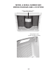
MODEL & SERIAL NUMBER AND WIRING DIAGRAM LABEL LOCATIONS Model & Serial Number Label (Behind Water Bucket) Wiring Diagram Label (Inside Front Half Of Cabinet) 1-3
— NOTES — 1-4
PRODUCT OPERATION THEORY OF OPERATION WHAT IS HUMIDITY? REMOVING UNWANTED HUMIDITY Humidity is defined as the amount of water vapor in the air and is measured as a percentage of the amount of water vapor the air can hold at a given temperature. When the amount of water vapor exceeds 100%, the moisture can no longer remain suspended in the air, usually resulting in precipitation. At levels approaching 100%, mist and fog are present.
OPERATING CHARACTERISTICS LOW TEMPERATURE OPERATION When a dehumidifier begins its run cycle, a partial frosting of the evaporator can be observed. This temporary frosting is limited by the operating conditions of the unit. In all cases, the frost should completely disappear within 10 to 15 minutes. In cool dry conditions, (65°F or lower temperatures, and relative humidity of 60% or less), the evaporator may become completely coated with frost or ice.
FAN SPEED: Controls the fan operation, as follows: High: For faster moisture removal Low: For slower moisture removal Auto Fan Speed (Electronic Models): Automatically sets the fan speed based on the relative humidity of the room. Low speed is used when the relative humidity is within 5% of the Desired Humidity setting. High speed is used when the relative humidity reaches or exceeds 5% of the Desired Humidity setting. on. If the relative humidity has not increased, the unit will only run for 3 minutes.
DEHUMIDIFIER USE SETTING THE CONTROLS (CONTROL TYPES 1 & 2 ONLY) Starting/Stopping the Dehumidifier NOTE: Before turning on the dehumidifier, be sure that the bucket is empty and fits all the way into the dehumidifier. Control Type 1 NOTE: Minimum operating temperature is 65ºF (18ºC). A Electrical Shock Hazard Plug into a grounded 3 prong outlet. Do not remove ground prong. Do not use an adapter. Do not use an extension cord. Failure to follow these instructions can result in death, fire, or electrical shock.
Dryness Control The Dryness Control regulates the amount of moisture in the room. Turn the control knob clockwise for more drying. Turn the control knob counterclockwise for less drying. Turn the control knob to “Dry” to maintain average humidity conditions. NOTE: For the first few days of use, turn the DRYNESS CONTROL clockwise to CONTINUOUS RUN to remove extra moisture from the furnishings as well as the room air. Electrical Shock Hazard Plug into a grounded 3 prong outlet. Do not remove ground prong.
DRAINING THE DEHUMIDIFIER • Auto —Will provide the maximum humidity control by automatically adjusting the fan speed and/or turning the dehumidifier on and off to maintain humidity setting. Desired Humidity (Control Type 3 Models Only) 1. Press DESIRED HUMIDITY to select the desired humidity setting. 2. Choose Normal, Dry, Max Dry or Continuous Run. • Normal—Will operate the dehumidifier at the selected fan speed until the humidity levels are lowered.
3. Pour water through opening into a sink or tub. 3. Attach a garden hose to drain hose connector on the inside of the dehumidifier. Hand tighten. A B A. Garden hose B. Drain hose connector 4. Place the other end of garden hose into a floor drain. Check to see that the hose lies flat and is in the drain. 5. Reinstall bucket. 4. Reinstall bucket. IMPORTANT: If the Empty/Adjust Bucket light comes on, the dehumidifier will not operate. Empty or adjust bucket.
DEHUMIDIFIER CARE CLEANING THE AIR FILTER (ON SOME MODELS) CLEANING THE DEHUMIDIFIER Exterior NOTE: Have an authorized service technician clean and service the interior coils of your product annually. 1. Turn off dehumidifier. 2. Dust front grille and side panels with a soft brush or the dusting attachment of your vacuum cleaner. The air filter is removable for easy cleaning. A clean filter helps remove dust, lint, and other particles from the air and is important for best operating efficiency.
COMPONENT ACCESS This section instructs you on how to service the Dehumidifier. The components and their locations are shown below. NOTE: The sealed system in the Dehumidifier is not serviced. COMPONENT LOCATIONS Electrical Shock Hazard Disconnect power before servicing. Replace all parts and panels before operating. Failure to do so can result in death or electrical shock.
REMOVING THE CABINET 3. 4. If present, pull the air filter down and out from behind the front louvers. Remove the two front screws from the front half of the cabinet. Electrical Shock Hazard Disconnect power before servicing. Replace all parts and panels before operating. Failure to do so can result in death or electrical shock. Air Filter Front Screws 1. 2. Unplug dehumidifier or disconnect power. Pull the water bucket out of the dehumidifier and remove it. 5.
6. Remove the bottom screw and the two top hex-head screws from the rear half of the cabinet. 7. Pull the front and rear halves of the cabinet from the dehumidifier and remove them.
REMOVING THE ELECTRONIC CONTROL, THERMISTOR, AND POWER SUPPLY CORD 3. Disconnect the four wire connectors from the electronic control. Electronic Control Electrical Shock Hazard Disconnect power before servicing. Replace all parts and panels before operating. Failure to do so can result in death or electrical shock. 1. 2. Unplug dehumidifier or disconnect power. Remove the cabinet from the dehumidifier (see page 3-2 for the procedure).
5. 6. Unclip the thermistor from the tubing and remove it. NOTE: Do not remove the thermistor from the clip. Remove the hex-head screw from the green ground wire. 9. Remove the power supply cord from the cabinet. Power Supply Cord Thermistor & Clip 10. Remove the wiring from the three tabs, and remove the electronic control assembly from the dehumidifier. Ground Wire Screw 7. 8. On the rear of the unit, disconnect the two wires from the bucket switch terminals and unclip the wires.
REMOVING THE MECHANICAL HUMIDISTAT, LIGHT, AND POWER SUPPLY CORD 5. Electrical Shock Hazard Disconnect power before servicing. Replace all parts and panels before operating. Failure to do so can result in death or electrical shock. 1. 2. 3. 4. Unsnap the four top cover tabs from the mechanical control and remove the cover. Top Cover Tabs Unplug dehumidifier or disconnect power. Remove the cabinet from the dehumidifier (see page 3-2 for the procedure). Pull the knob off the humidistat shaft.
8. To remove the power supply cord: a) Disconnect the white power supply cord wire from the compressor capacitor terminal. b) Disconnect the black power supply cord wire from the COM terminal of the bucket switch. c) Remove the hex-head screw from the green ground wire at the top of the condenser. Bucket Switch Condenser BK (COM) Wire WH Wire Ground Wire Screw Compressor Capacitor d) Remove the power supply cord from the dehumidifier.
REMOVING THE FAN CAPACITOR AND THE FAN MOTOR 4. Brown Wires Electrical Shock Hazard Disconnect power before servicing. Replace all parts and panels before operating. Failure to do so can result in death or electrical shock. 1. 2. To remove the fan motor: a) Loosen the T-20 Torx screw and pull the blower off the fan motor shaft. Capacitor Screw Unplug dehumidifier or disconnect power. Remove the cabinet from the dehumidifier (see page 3-2 for the procedure).
• Top green ground wire on condenser. c) Remove the three 5/16˝ hex-head screws from the fan motor, then pull the wiring out of the access hole and remove the motor.
REMOVING THE COMPRESSOR CAPACITOR AND THE BUCKET SWITCH 3. Electrical Shock Hazard Disconnect power before servicing. Replace all parts and panels before operating. To remove the compressor capacitor: a) IMPORTANT: Discharge the capacitor by touching the leads of a 20,000 ohm resistor to the capacitor terminals. b) Disconnect the three wires (electronic control models), or four wires (mechanical models) from the capacitor terminals. c) Remove the screw from the capacitor.
4. To remove the bucket switch: Electronic Model: a) Disconnect the two black wires from the N.C. and COM switch terminals. c) Press the locking tab, push the switch holder through the cutout, and remove it from the dehumidifier. Mechanical Models: b) Disconnect the black (COM), tan (N.O.), and yellow (N.C.) wires from the switch terminals. Bucket Switch Switch Holder Press Tab & Push In d) Unclip the bucket switch and remove it from the holder. BK (N.C.
— NOTES — 3-12
COMPONENT TESTING • Check all connections before replacing components, looking for broken or loose wires, failed terminals, or wires not pressed into connectors far enough. • Resistance checks must be made with power cord unplugged from outlet, and with wiring harness or connectors discon- Before testing any of the components, perform the following checks: • The most common cause for control failure is corrosion on connectors.
Electrical Shock Hazard Disconnect power before servicing. Replace all parts and panels before operating. Failure to do so can result in death or electrical shock. FAN MOTOR BUCKET SWITCH Actuator N.C. N.O. Refer to page 3-8 for the procedure for accessing the fan motor. 1. Unplug dehumidifier or disconnect power. 2. IMPORTANT: Discharge the capacitor by touching the leads of a 20,000 ohm resistor to the capacitor terminals. 3. Disconnect the fan motor wires from the capacitor terminals. 4.
DIAGNOSTICS & TROUBLESHOOTING DIAGNOSTICS 1. Turn off the dehumidifier with the power button. • If you press a wrong key during the 3-key sequence, or if more than 5 seconds elapses before completing the sequence, you will need to restart the sequence from the beginning. • After pressing the 3 keys in the correct order within 5 seconds, all the LEDs will light at Step 1 (see chart). Use the Desired Humidity key to advance the steps. Using any other key will exit diagnostics. 2. Remove the bucket. 3.
TROUBLESHOOTING Electrical Shock Hazard Disconnect power before servicing. Replace all parts and panels before operating. Failure to do so can result in death or electrical shock. PROBLEM Unit will not run - no fan and no compressor. Fan runs - compressor does not run. CAUSE CORRECTION 1. Unit not turned “ON” or not set dry enough. 1. Set control to “CONTINUOUS.” This will allow the fan and compressor to run regardless of the ambient humidity. 2. No power to unit. 2a.
WIRING DIAGRAMS WIRING DIAGRAM 1 6-1
WIRING DIAGRAM 2 6-2
WIRING DIAGRAM 3 6-3
— NOTES — 6-4
— NOTES — 6-5
— NOTES — 6-6
PRODUCT SPECIFICATIONS AND WARRANTY INFORMATION SOURCES IN THE UNITED STATES: FOR PRODUCT SPECIFICATIONS AND WARANTY INFORMATION CALL: FOR WHIRLPOOL PRODUCTS: 1-800-253-1301 FOR KITCHENAID PRODUCTS: 1-800-422-1230 FOR ROPER PRODUCTS: 1-800-447-6737 FOR TECHNICAL ASSISTANCE WHILE AT THE CUSTOMER’S HOME CALL: THE TECHNICAL ASSISTANCE LINE: 1-800-253-2870 HAVE YOUR STORE NUMBER READY TO IDENTIFY YOU AS AN AUTHORIZED SERVICER FOR LITERATURE ORDERS: PHONE: 1-800-851-4605 FOR TECHNICAL INFORMATION AND SERVICE POI
CORPORATION