
Installation

R
R
R
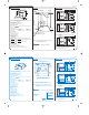
1 MOVING THE PRODUCT INTO THE CAVITY
(page 5 of 8)
PLEASE NOTE: Your model of may differ from the model shown in the installation diagrams. Installation is similar for Integrated & Prefinished products for either Single or Double models.
Information referring to Single models only is highlighted in blue. Installation diagrams have been simplified to enable clearer instruction. FOR INTEGRATED PRODUCTS FOLLOW THE INTEGRATED PANEL PREPARATION
INSTRUCTIONS, BEFORE MOVING THE PRODUCT INTO THE CAVITY.
INSTALLATION INSTRUCTIONS
READ THESE INSTRUCTIONS
COMPLETELY AND CAREFULLY.
must be free to close completely.
With overlapping integrated drawer fronts
a 2.5mm clearance must be maintained
between drawer front and cabinetry.
DO NOT push
middle of
drawers.
Be careful of
sharp edges.
MOUNTING TAB OPTIONS
The mounting tabs are in pairs, one on each side of the product. They
are used to secure the product to the cavity sides. Installation requires
two sets of tab pairs be used, for example
A and B tab pairs. All tabs
would be optimum. A minimum installation requires that the
B
mounting tabs be used.
DOUBLE MODELS ONLY
C Mounting Tab Option
If the top installation tabs
C are to be used, fit to the chassis by
inserting into the top slots as shown. Ensure the tabs are fully
locked in place.
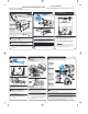
Check cavity for any obstructions that may interfere with sliding the
product back. Loosen the feet DOUBLE MODELS ONLY.
Push product into cavity to suit adjacent cabinetry. Do not push
middle of drawer(s). Ensure inlet, drain hose(s) and power supply
cord are not restricted or damaged by carefully pulling them
through the services hole, while the product is being pushed back
into the cavity.
1
2
3
2 REMOVING THE TUB
(SINGLE MODELS ONLY). The product
may move. Mark chassis position on
cavity.
SINGLE MODELS ONLY. Gently open the drawer and mark
the chassis position on the cavity, before removing the
tub.
Open the drawer (Bottom drawer in DOUBLE MODELS).
Release the tub by depressing the right hand tub clip and
pushing it back 30mm. Repeat on the left hand side.
Lift the tub up off the drawer runners.
Slide both runners back into the product.
Place the tub onto the floor.
For SINGLE MODELS, depending on the height of the
cavity, the tub will need to be supported, eg. on a chair.
4
5
6
1
3
2
4
8
6
5
7
8
7
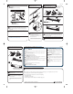
DOUBLE MODELS ONLY
Adjust the height of the product to suit the cabinetry, by
turning the feet from inside the product using a wrench or
M5 socket. TIP - gently take the load off each foot using
the slide and then turn by hand.
NOTE: For integrated products, align the top of the
upper panel with the top of the adjacent cabinetry.
The product must be levelled to within 2.5mm from
front to back, and side to side. TIP - Place a spirit level
on the drawer runners to level the product.
9
9
The product should NOT support
any part of the kitchen cabinetry.
4 SECURING THE PRODUCT
SINGLE MODELS ONLY
Check the position of the chassis is still where
marked on the cavity, before securing the
product.
There are four 16mm round holes, two on the
left and right hand side of the sound
insulation. To secure the product to the
cabinetry use a 16mm Phillips screw in each
hole.
DOUBLE MODELS ONLY
Screw the two top tabs to the underside of
bench. Use the supplied Phillips 16mm screws.
Tabs can accommodate a maximum of 19mm
vertical gap.
10
11
12
NOTE - SINGLE MODELS do
not have top tabs.
5 REFITTING THE TUB
While the tub is removed, it can be rotated or
turned upside down. This will cause the hoses to
become twisted. Reverse the direction to unwind
the hoses before refitting the tub.
To refit the tub, make sure both of the latches at
the rear of each drawer runner are facing forward.
Ensure hoses are hooping upward. Place the tub on
the half open drawer runners and close the drawer.
Check the tub clips have reset on both sides of the
tub. If not, pull the tub clips forward until the tub
clip button is reset.
13
14
Before refitting the tub, ensure the hoses are not
twisted and the latches at the rear of each drawer
runner are facing forward.
Ensure the tub clips on both sides are reset.
10
11
12
13
14
6 CONNECTING THE DRAIN HOSE(S)
Slip a wire clip over each drain hose, then push the hoses into the Drain Hose
Joiner firmly, 5 clicks. Position the wire clip(s) between the two positioning ribs
on the Drain Hose Joiner.
Attach the Drain Hose Joiner to the waste tee (see Plumbing Options). Ensure a
snug fit. If required a hose clamp may be used.
When using the standpipe option (see Plumbing Options), hose(s) should not
extend further than 120mm down the standpipe, in order to prevent siphoning.
Attach the Drain Hose Support to the cabinetry (with the screw supplied) to
prevent siphoning and to keep the drain hose(s) from kinking. If required, the
Drain Hose(s) may be trimmed to a suitable length.
15a
with Hose Joiner (see Plumbing Options).
Remember to slip the wire clip(s) on the drain hose(s) first.
Ensure the Drain
Hose(s) are fully
extended.
16
15a
15b
15b
16
(page 6 of 8)
3 ADJUSTING THE FEET
DOUBLE MODELS ONLY
MINIMUM CLEARANCE TO
UNDERSIDE OF COUNTER 2.5mm
Drain Hose joiner
MUST NOT sup-
port weight of
hoses. Keep
excess length of
Drain Hose on the
side
of the Drain Hose
support.
R
Minimum hole size
to be connected
to the drain sys-
tem is 16mm.
The Drain Hose
support must be
used.
1Gb00079 28-11-2002 18:50 Pagina 3