LC3000 Laundry Reader Installation and Setup Guide
The following information applies to wired LC3000 systems equipped with LCM20s only. Blackboard Inc. LC3000 Tested To Comply With FCC Standards FOR HOME OR OFFICE USE This Class A digital apparatus complies with Canadian ICES-003 The following information applies to wireless systems equipped with LWIs and LE3/BRIDGES only. Blackboard Inc. LWI30xx Tested To Comply With FCC Standards FOR HOME OR OFFICE USE This device complies with Part 15 of the FCC Rules.
Contents 1 LC3000 LAUNDRY CENTER INSTALLATION 4 4 Laundry Center Components LC3000 Components 5 Laundry Center Installation Overview 6 LC3000 LAUNDRY READER INSTALLATION 7 Install the LC3000 Enclosure 9 10 11 11 LC3000 Laundry Reader Configuration Configure LC3000 Reader using front panel Configure LC3000 Reader using RS-232 Configure LC3000 Reader using Telnet 12 Comm Mode Selection 13 WIRED LAUNDRY MACHINE INTERFACE INSTALLATION 15 Laundry Controller Multiplexer (LCM20) Installation 15 Install th
Contents 32 APPENDIX 32 Features 33 Transaction Process 35 Manager Menus 37 Laundry Components Dimensions and Weight 40 LC3000 Laundry Reader Default Configuration Settings 40 Restore Default Settings 41 MW9010/MW9012 Laundry Reader Retrofit 41 Configure LC3000 for retrofit (wired laundry centers only) PRINTED OCTOBER 6, 2009 II
Figures Figure 1-1 Wired LC3000 Laundry Center Solution2 Figure 1-2 Wireless Laundry Center Solution3 Figure 1-3 Mounting & Knockouts7 Figure 1-4 Power Installation7 Figure 1-5 Power Connections8 Figure 1-6 LC3000 Laundry Reader Configuration10 Figure 1-7 Front panel configuration10 Figure 1-8 LC3000 Configuration Menu11 Figure 1-9 LC3000 Laundry Center Solution14 Figure 1-10 LCM20 in LC300015 Figure 1-11 LCM20 Connections16 Figure 1-12 Power Supply access16 Figure 1-13 Power Connec
LC3000 LAUNDRY READER INSTALLATION GUIDE D OCUMENT 1 1 3 5 REV 03 LC3000 L AUNDRY C ENTER I N S TALL A T IO N This manual provides instructions for selecting, installing, and configuring the Blackboard Laundry Center using the LC3000 Laundry Reader. The LC3000 Laundry Reader controls laundry machines across a laundry Center network and Blackboard Transaction System (BbTS) and communicates with the user interface through a display, keypad, and magstripe reader.
LC3000 LAUNDRY CENTER INSTALLATION WIRED SOLUTION The wired solution reader supports up to 60 laundry machines across three connected Multiplexers. The first Multiplexer is installed inside the LC3000. Each machine uses a Laundry Controller Interface (LCI), a wiring harness inside the machine, to facilitate communications between the laundry machine controller and LC3000 Laundry Reader.
LC3000 LAUNDRY READER INSTALLATION GUIDE D OCUMENT 1 1 3 5 REV 03 WIRELESS SOLUTION Up to 60 laundry machines can be connected wirelessly to the LC3000 using a Wireless Bridge (LE3/ BRIDGE). Each Bridge communicates with laundry machines within 60 feet. Multiple Wireless Bridges can be used if stone or metal obstructions reduce the range. Each laundry machine connects to a Laundry Wireless Interface installed inside the machine.
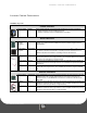
LAUNDRY CENTER COMPONENTS LAUNDRY CENTER C OMPONENTS LC3000 Components COMMON COMPONENT Laundry Reader LC3000 Each LC3000 supports up to 60 machines (stacked units count as 2 machines). Wired installations require LCM20(s) and LCIs. Wireless installations require LE3/BRIDGE(s) and LWI(s). WIRED COMPONENTS Laundry Controller Multiplexer LCM20 Power Supply / Enclosure LE3/PSENCL An LE3/PSENCL power supply/enclosure is required for the 2nd and 3rd LCM20s.
LC3000 LAUNDRY READER INSTALLATION GUIDE D OCUMENT 1 1 3 5 REV 03 LAUNDRY CENTER I NSTALLATION O VERVIEW 1 Configure Laundry Machines in BbTS.
LC3000 LAUNDRY READER INSTALLATION LC3000 L AUNDRY R EADER I NSTA LLATION The LC3000 Laundry Reader must be mounted on a wall in a location that is convenient to cardholders and wiring requirements. LC3000 MOUNTING LOCATION CONSIDERATIONS • 120 VAC power availability Connect to 120 VAC @ 60 Hz. Connect only to a 15A maximum branch circuit protection or equivalent. Use a circuit breaker or switch to disconnect power when installing or removing the LC3000.
LC3000 LAUNDRY READER INSTALLATION GUIDE D OCUMENT 1 1 3 5 REV 03 PREPARE ENCLOSURE The Reader can be mounted flush to the wall with wiring behind the wall; or it can be surface- AC power knockouts machine wires flush-mount mounted with wiring in conduit exterior of the wall. Before mounting the enclosure, remove knockouts ACMAIN necessary for routing wires and/or attaching conduits. Remove only the knockouts required for your installation. • AC power knockouts accept 1/2'' conduit fittings.
LC3000 LAUNDRY READER INSTALLATION 8 Install wires into the AC terminal block as shown in Figure 1-5, tighten the screws to 5 - 7 in-lbs., and replace power supply cover. Ensure 120VAC wiring is confined within power supply compartment when cover is reinstalled to maintain UL compliance. 9 Line Neutral Ground Reconnect external AC power. 10 Connect to Network. The LC3000 provides for both 10/100 Base-T, TCP/IP and RS-485 BbTS network connections.
LC3000 LAUNDRY READER INSTALLATION GUIDE D OCUMENT 1 1 3 5 REV 03 LC3000 L AUNDRY READER C ONFIGURATION The Laundry Reader must be configured to communicate with the BbTS network.
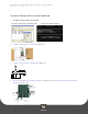
LC3000 LAUNDRY READER CONFIGURATION LC3000Config Figure 1-6 LC3000 Laundry Reader MAC Address IP Address DHCP Status IP Communications RS-485Communications Communication Mode Reader Address BaudRate Enabled DHCP HostDHCP TelnetEnable Service Card Enable Disabled Disable IP Address Save Subnet Mask Default Router/ Gateway Host IP Address OFFLINE: An asterisk (*) in the first line, second to the last position indicates the terminal is offline.
LC3000 LAUNDRY READER INSTALLATION GUIDE D OCUMENT 1 1 3 5 3 REV 03 Press NEXT when the End of Config Setup message displays, this saves the settings and reboot the reader. The terminal may be offline for several minutes until it synchronizes with the Host. Configure LC3000 Reader using RS-232 4 Connect a cable from a computer’s serial port to the port on the LC3000 door labelled “RS-232 CONFIG”. IPrdr4U See: RS-232 Config Port Connections (Page: 11). 5 6 Open a terminal program (e.g.
COMM M ODE SELECTION COMM MODE S ELECTION OVERVIEW The ‘Comm Mode’ selections on the CR3000, LC3000 and VR/MDBMP have been changed a few times in the history of the products. When a given communication mode is selected, the unit reboots and starts a specific software executable type based on the communication mode chosen.
LC3000 LAUNDRY READER INSTALLATION GUIDE D OCUMENT 1 1 3 5 REV 03 W IRED L AUNDRY M ACHINE I NTERFACE I NSTALLATION WIRED INSTALLATION OVERVIEW • Install the LCM20 in the LC3000 (page 1-15) • Install External LCM20(s) (if required) (page 1-16) Only laundry centers with more than 20 laundry machines need External LCM20s. Each LCM20 communicates with up to 20 laundry machines.
WIRED LAUNDRY MACHINE INTERFACE INSTALLATION Campus Network Belden 8723, 5502UE cable or equivalent Laundry Reader (LC3000) w/ Multiplexer (LMC20) Multiplexer (LCM20) w/ Enclosure (LE3/PSENCL) Multiplexer (LCM20) w/ Enclosure (LE3/PS n 8723, 5502UE cable uivalent max) 1 ---------------------- 20 21 -------------------- 40 41 -------------------- 60 Laundry Center Interface (LCI) installed in each machine Figure 1-9 LC3000 Laundry Center Solution PRINTED OCTOBER 6, 2009 1-14
LC3000 LAUNDRY READER INSTALLATION GUIDE D OCUMENT 1 1 3 5 REV 03 LAUNDRY CONTROLLER MULTIPLEXER (LCM20) INSTALLATION LCM20 PLACEMENT CONSIDERATIONS • 120 VAC power availability Connect to 120 VAC @ 60 Hz. Connect only to a 15A maximum branch circuit protection or equivalent. Use a circuit breaker or switch to disconnect power when installing or removing the LC3000.
LAUNDRY CONTROLLER M ULTIPLEXER (LCM 20) INSTALLATION Do not connect power to the LCM20 Board until all machine interfaces are terminated. 0 EF 1 2 3 D C 4 B 5 A9 6 87 ACMAIN LNG LINK/ACT NET 100M HOST RS-485 LCM20 RS-485 BRIDGE RS-485 AUX RS-485 Power RS-232 LWI CONFIG CONFIG to external LCM20 (Belden 5502UE cable or equivalent) Figure 1-11 LCM20 Connections Install External LCM20(s) (if required) If your Laundry Center has more than 20 machines, an external LCM20 and LE3/PSENCL are required.
LC3000 LAUNDRY READER INSTALLATION GUIDE D OCUMENT 1 1 3 5 8 REV 03 Strip back AC wire insulation .28", install wires into AC terminal block as shown in Figure 1-13, tighten screws to 5-7 in-lbs., and replace power supply cover. Line Neutral Ground Prevent bare wire from being exposed when installed in the AC terminal block. UL compliance: Ensure 120VAC wiring is within power supply compartment when cover is replaced.
LAUNDRY CONTROLLER INTERFACE (L CI) INSTALLATION LAUNDRY CONTROLLER I NTERFACE (LCI) I NSTALLATION The Laundry Controller Interface (LCI) is installed inside each laundry machine. The Laundry Controller Interface (LCI) is a wiring harness that connects to the laundry machine controller. The LCI is then connected to the Laundry Controller Multiplexer (LCM20) to communicate with Laundry Reader. The Laundry Controller Interface (LCI) model used depends on the laundry machine manufacturer.
LC3000 LAUNDRY READER INSTALLATION GUIDE D OCUMENT 1 1 3 5 REV 03 2 Route the 4-conductor cable from the LCM20 into the laundry machine for connection to the LCI. 3 Attach female connectors from the hardware kit to the machine end of the 4-conductor cable. 4 Insert the LCI male bullet connectors into the female connectors of the 4-conductor cable (white to white, black to black, etc.) see: Figure 1-15. Stacked Machine: connect the two-wire harness to the black and green wires, as shown.
LAUNDRY CONTROLLER INTERFACE (L CI) INSTALLATION Install Alliance/Speed Queen LCI3020 in Laundry Machine Two LCI3020s must be ordered when wiring to a stacked dryer. Laundry Controller Multiplexer (LCM20) Speed Queen Laundry Machine white 4-pin Molex 4 black 3 red 2 black 1 white 1 2 black 3 white 4 red red black BELDEN 8723 or equivalent 4-conductor cable green green Figure 1-17 Alliance/Speed Queen Machine (LCI3020) 8 Remove the operator console from the machine.
LC3000 LAUNDRY READER INSTALLATION GUIDE D OCUMENT 1 1 3 5 REV 03 Install Whirlpool LCI3030 in Laundry Machine Stacked dryers require two LCI3030s. Laundry Controller Multiplexer (LCM20) Whirlpool Advantech Laundry Machine 1 2 black 3 white 4 black M2 red red white COIN 1 green BELDEN 8723 or equivalent 4-conductor cable green Figure 1-18 Whirlpool/Advantech Single Machine (LCI3030) 15 Remove the operator console from the machine. Refer to Whirlpool service manual.
WIRELESS LAUNDRY MACHINE INTERFACE INSTALLATION W I R E L E S S L AUNDRY M A C H I N E I NTERFACE I NSTALLATION WIRELESS LAUNDRY CENTER INSTALLATION OVERVIEW • Configure laundry machines in BbTS and download configurations to the Reader. See: the BbTS Reference Manual (Unix), or the BbTS System Administration Guide (UE). • Configure the LE3/BRIDGE (page 1-23) • Install the LE3/BRIDGE (page 1-24) • Configure the LWI Module (page 1-25) Each laundry machine is assigned a number between 1 and 60.
LC3000 LAUNDRY READER INSTALLATION GUIDE D OCUMENT 1 1 3 5 REV 03 All washers and dryers must be defined at the host server before the LWI modules can be configured. The machine type (washer/dryer), manufacturer, and stack configuration are included in the host server configuration options. WIRELESS B RIDGE LE3/BRIDGE INSTALLATION The LE3/Bridge module must be configured prior to being installed. This requires programming a network ID and configuring the module as a Bridge.
WIRELESS BRIDGE LE3/BRIDGE INSTALLATION Note: Always select a network ID that has not been chosen on a nearby LC3000 Laundry Center wireless network. A nearby network is considered any installation within the same building and/or less then 500 feet. 7 Set the LWI type by selecting 2 to configure the module as a Bridge. 8 Remove the module from the 22-pin Molex connector.
LC3000 LAUNDRY READER INSTALLATION GUIDE D OCUMENT 1 1 3 5 6 REV 03 Verify communication between the Bridge module and LC3000 Reader using the status LED. The LED should be blinking approximately once every second. Install the cover onto the plastic enclosure to enclose the cable and module. The wire antenna must be slightly arced when the cover is installed.
LAUNDRY WIRELESS INTERFACE MODULE (LWI) INSTALLATION 3 Plug the 22-pin connector into the mating connector of the LWI module. The LC3000 Reader will detect the LWI module. The top two lines of the display show the machine ID, software version and network ID. The factory default for the network ID and machine ID is FF. If the LWI module has previously been assigned, the message Already Assigned is displayed. In all cases, enter 1 for yes, to reassign the network ID and/or machine ID.
LC3000 LAUNDRY READER INSTALLATION GUIDE D OCUMENT 1 1 3 5 REV 03 I NSTALL THE LWI3010 M ODULE MAYTAG LAUNDRY MACHINES FOR Status LED Transmit LED Maytag laundry machines require an LWI3010 module. A single LWI3010 will support both single washer/dryer Error LED machines and stacked dryer machines. Disconnect all power to the machines. 1 Figure 1-22 LWI wireless module Remove the operator console (with display and switches) from the machine. Single machine: remove only the top two screws.
INSTALL THE L WI302 0 MODULE FOR ALLIANCE/SPEED Q UEEN LAUNDRY MACHINE S AA3 AA2 Stacked machine only LWI wireless module Figure 1-23 LWI3010 installation in Maytag laundry machine I NSTALL THE MACHINES LWI3020 M ODULE FOR ALLIANCE/SPEED QUEEN LAUNDRY Alliance/Speed Queen laundry machines require an LWI3020 module. A single LWI3020 will support both single washer/dryer machines and stacked dryer machines.
LC3000 LAUNDRY READER INSTALLATION GUIDE D OCUMENT 1 1 3 5 REV 03 When installing the LWI3020 onto a stacked machine, the P2 connector must be installed into the control board of the even numbered machine. For example, if the stacked machine will be assigned machines 3 and 4 within the laundry center, then the P1 connector would be installed in the control board identified as machine 3 and the P2 connector must be installed in the control board of the machine identified as machine 4.
WIRELESS MODULE TROUBLESHOOTING AND OPERATION WIRELESS M ODULE TROUBLESHOOTING AND OPERATION BRIDGE MODULE: The Red STATUS LED located near the center of the board blinks when a message is received from the LC3000 Reader. Status LED Communication is over RS-485. When the bridge is attached to the LC3000 Reader, the red status LED should blink once Transmit LED per second.
LC3000 LAUNDRY READER INSTALLATION GUIDE D OCUMENT 1 1 3 5 REV 03 LWI MODULE: The Red STATUS LED located near the center of the board blinks when a message is received from the Bridge. The Status LED frequency of the blinking depends on the number of LWI modules configured on the Bridge. As more modules are Transmit LED added, the blink rate decreases. Error LED The Green TRANSMIT LED located near the edge of the board is turned on whenever a radio packet is being transmitted by the LWI module.
APPENDIX A PPENDIX FEATURES • Interfaces to: Maytag commercial “debit-card” ready, Speed Queen NetMaster and MDC, and Whirlpool Advantech laundry machines • TCP/IP and wireless protocols encrypted using AES • Configuration via keypad/display, CONFIG port or telnet • Keypad (Service Card) configuration can be disabled • Telnet access can be disabled • Stores up to 40,000 transactions offline • Displays balance, account warnings and other messages following transactions • Adjustable volume s
LC3000 LAUNDRY READER INSTALLATION GUIDE D OCUMENT 1 1 3 5 REV 03 TRANSACTION P ROCESS The LC3000 Laundry Reader displays cardholder instructions. When idle, the reader display toggles between instructions and machines available. Offline messages are only displayed if offline operations are allowed in the reader configuration at the host and card number is valid. TRANSACTION PROCESS 1 Select a machine by using the Reader’s numeric keypad, and press Enter.
TRANSACTION PROCESS 4 Select a machine by using the Reader’s numeric keypad, and then press Enter. The machine number, Total Cost (the amount that will be charged for the original cycle plus any additional cycles), and cost of an additional cycle is displayed. 5 Press the Add Time softkey to display the cost and time (in minutes) of an additional cycle. Pressing Add Time again multiplies the additional dry time and increases the Total Cost to reflect the Total Transaction amount.
LC3000 LAUNDRY READER INSTALLATION GUIDE D OCUMENT 1 1 3 5 REV 03 MANAGER MENUS The Manager Card is used to access LC3000 Laundry Reader menus for sales data and modifying reader settings. Manager Menus Swipe Manager Card 1. Sales Totals 2. Terminal Setup 3. Machine Service 4. Bridge Status 5.
MANAGER MENUS Table 1-2: Bridge Status Display Message Description Not Defined This Bridge is not configured by the LWI CONFIG port. No Bridge Comm This Bridge is configured, but is not successfully communicating with the BRIDGE RS-485 port. No LWIs Defined This Bridge is successfully communicating with the BRIDGE RS-485 port, but no LWIs are defined for this Bridge. No LWI Communication One or more LWIs are defined for this Bridge, but no LWI communication exists.
LC3000 LAUNDRY READER INSTALLATION GUIDE D OCUMENT 1 1 3 5 REV 03 LAUNDRY COMPONENTS D IMENSIONS • LC3000: 9.6" H x 7.92'' W x 3.3" D, 7.6 lbs. • LE3/PSENCL: 9.6" H x 7.92" W x 3.3" D, 7.6 lbs. • LE3/BRIDGE: 4.5" H x 4.5" W x 2" D, 1.0 lb. • LWI30XX: 3" H x 3" W X 1.5" D, 1.0 lb. AND WEIGHT 9.660'' 8.940'' 8.840'' Mount ACMAIN Mount 6.360'' 3.360'' Mount Mount 0.940'' 0.000'' 7.920'' 7.220'' 6.270'' 4.200 1.200 0.720'' 0.
LAUNDRY COMPONENTS DIMENSIONS AND WEIGHT Table 1-3: LC3000 Component Specifications Power Operating Environment LC3000 Non-Operating Environment Power LE3/PSENCL with LCM20 Operating Environment Non-Operating Environment Power Operating Environment LE3/BRIDGE Non-Operating Environment Power Operating Environment LWI3xxx Non-Operating Environment Input Voltage Range Input Frequency Input Current Temperature Relative Humidity Altitude Temperature Relative Humidity Altitude Input Voltage Range Input Fr
LC3000 LAUNDRY READER INSTALLATION GUIDE D OCUMENT 1 1 3 5 REV 03 Power Supply: Replacing the power supply, if necessary, is simplified with a magnetic or clip screwdriver, such as the Craftsman No. 1 x 4 inch screwdriver shown. (Sears, item #00941362000, model #41362.
LC3000 LAUNDRY READER DEFAULT CONFIGURATION SETTINGS LC3000 L AUNDRY READER D EFAULT CONFIGURATION S ETTINGS The LC3000 Laundry Reader’s default settings are: • DHCP enabled • NP (host) IP address assigned by DHCP server Restore Default Settings Forget your password? Restore Default Settings. 1 Connect a cable from a computer’s serial port to the one labelled “RS-232 CONFIG”. Cable connections are shown in RS-232 Config Port Connections (Page: 11) (Page 8).
LC3000 LAUNDRY READER INSTALLATION GUIDE D OCUMENT 1 1 3 5 REV 03 MW9010/MW9012 LAUNDRY READER RETROFIT BbTS Unix laundry centers with existing MW9010/MW9012 Laundry Readers can upgrade to the LC3000 Laundry Reader. Upgrading the Reader does not require wiring, LCM2s or laundry machine interface replacements. The LC3000, as shipped from Blackboard, is configured for up to 60 machines on up to 3 LCM20s.