
Instruction for Use


N C
M Y
ENVIRONMENTAL HINTS
Packing
Do not throw the packing into the garbage: first sort out the diffe-
rent materials (i.e.: steel, cardboard, polystyrene) following local
regulations.
Conformity declaration
This appliance incorporates parts intended to come
into contact with foodstuffs in compliance with EEC di-
rective 89/09/CEE.
INSTALLATION
The appliance must not be used in outside environments.
The appliance must not be positioned in a humid environment or
in areas where water jets may be used. In the ice bin of this appli-
ance you will find the following accessories: instructions for use,
an envelope containing an ice pallet, a funnel with hose for perio-
dical cleaning, 4 adjustable feet and washers.
− Fit the feet into the receptacles, proceeding as follows:
− Screw the 4 threaded supports on the bottom front and screw
the adjustable feet on the supports
(Fig. ).
− Place the ice maker on a stable, level surface and adjust the
feet if necessary.
− Do not install the unit close to a heat source, in a niche, or lea-
ning against a wall on one side; air must be free to circulate
through the ventilation grids (vicinity not less than 6 cm).
− In rooms with an ambient temperature lower than +10
o
Cor
higher than +32
o
C, ice cubes production is not guaranteed. Ho-
wever, at ambient temperatures from +16
o
Cto+32
o
C, ice cubes
production can be guaranteed if a tropicalized unit is installed.
ELECTRICAL CONNECTION
Check that the voltage on the rating plate corresponds to the vol-
tage in your home
(Fig. 2).
Connect the appliance to the mains and ensure that it is working
correctly before storing food.
The earthing of this appliance is compulsory by law.
− The electrical and plumbing connection must be carried out by
a qualified technician, in compliance with local safety regulations.
The manufacturer will accept no liability for damage to persons or
objects arising from the non-observance of this requirement.
ELECTRICAL INFORMATION
“WARNING - THIS APPLIANCE MUST BE EARTHED”
(For Great Britain only)
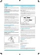
Fuse replacement.
If the mains lead of this appliance is fitted with a BS 1363A 13
amp fused plug, to change a fuse in this type of plug use an
A.S.T.A. approved fuse to BS 1362 type and proceed as follows:
1. Remove the fuse cover (A) and fuse (B).
2. Fit replacement 13A fuse into fuse cover.
3. Refit both into plug.
IMPORTANT:
The fuse cover must be refitted when chan-
ging a fuse and
if the fuse cover is lost the plug must not be used
until a correct replacement is fitted.
Correct replacement are identified by the colour insert or the co-
lour embossed in words on the base of the plug.
Replacement fuse covers are available from your local electrical
store.
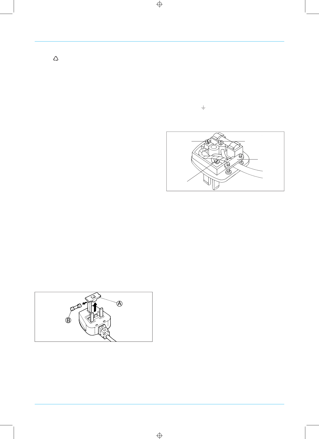
CONNECTION TO A REWIREABLE PLUG
If the fitted plug is not suitable for your socket outlet, then it should
be cut off and disposed of in order to avoid a possible shock ha-
zard should it be inserted into a 13A socket elsewhere. A suitable
altenative plug should then be fitted to the cable. The wires in this
mains lead are coloured in accordance with the following code;
BLUE - “NEUTRAL” (“N”)
BROWN - “LIVE” (“L”)
GREEN AND YELLOW - “EARTH” (“E”)
1.
The GREEN AND YELLOW wire must be connected to the
terminal in the plug which is marked with the letter “E” or by
the Earth symbol
or coloured green or green and yellow.
2. The BLUE wire must be connected to the terminal which is
marked with the letter “N” or coloured black.
3. The BROWN wire must be connected to the terminal which is
marked with the letter “L” or coloured red.
For the Republic of Ireland only
The information given in respect of Great Britain will frequently
apply, but a third type of plug and socket is also used, the 2-pin,
side earth type. In this case, the wire which is coloured GREEN
AND YELLOW must be connected to the EARTH contact, and the
other two wires to the two pins, irrespective of colour. The supply
to the socket must be fitted with a 16 amp fuse.
GREEN AND
YELLOW (“E”)
BROWN (“L”)
CABLE CLAMP.
BLUE (“N”)
Connection to a
typical13ampplug
PLUMBING CONNECTION
− Connect the water and drain hoses through the rear wall of the
unit
(Fig. 3).
− Connect the water inlet hose to a cold water tap, having a 3/4”
BSP thread. The outlet hose is to be placed into a drain, preferably
equipped with an S - trap to prevent any odour back-up. The drain
must be at a lower level than the outlet of the hose from the appli-
ance.
− The outlet hose should be inclined at least 10 degrees so the
water can drain naturally.
− If the water is very hard (rich in calcium and magnesium salts),
insert a softener-filter on the inlet connection between the tap and
the hose. This filter brings the water hardness to a normal value.
− Regenerate
or replace the water-softener filter (according to
the type) when the ice cubes are not completely transparent or
production time is increased. This appliance conforms to EEC di-
rective N
o
82/499/EEC on radiointerference.
English
4
CONTROLS
Fig. 2:
A) Water drain connection
Fig. 6:
A) Grid fuse
B) Ice-cubes level thermostat
C) Ice-cubes thickness thermostat
D) Water inlet connection
Fig. 10:
A) On/off switch (green)
B) Wash switch (blue)
OPERATION
Ice maker operation is completely automatic. Ice is formed by
progressive refrigeration of a film of water which flows on a refri-
gerated inclined plate
(Fig. 4).
When the ice film attains the re-