063_03 03/2006 Instructions for installation, use and maintenance GAS KITCHENS AGB AGB AGB AGB AGB AGB AGB 350/WP • AGB 352/WP 353/WP 351/WP 354/WP 358/WP • AGB 359/WP 360/WP • AGB 361/WP 362/WP • AGB 363/WP
CHARACTERISTICS Supplied by: Date: Customer Service: FAX e-mail 063_03 - GAS KITCHENS 03/2006 2 · 22
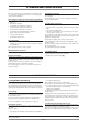
INDEX 1 Diagram 4 2 Features of the appliances 7 3 Technical data 7-8 4 Installation instructions 4.1 Safety rules 4.2 Structure, framework and safety devices of the appliances 4.2.1 Cooking zone 4.2.2 Oven Gas version GN 2/1 and MAXI Gas version GN 1/1 ventilated Electric version GN 2/1 Electric version GN 1/1 ventilated 4.2.3 Neutral cabinet 4.3 Assembly 4.3.1 Installation premises 4.3.2 Statutory regulations and technical requirements 4.3.3 Installation 4.3.4 Installation operations 4.3.
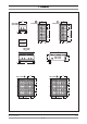
1 - DIAGRAM 800 900 300 AGB 350/WP AGB 351/WP AGB 352/WP 3/4" 970 AGB 350/WP AGB 351/WP AGB 352/WP 900 150 3/4" 21 100 150 21 53 53 694 52 706 AGB 350/WP AGB 351/WP 142 AGB 352/WP 295 9.5 kW 680 9.5 kW 295 9.5 kW 680 590 9.5 kW 590 350 350 3/4" 9.5 kW 4.0 kW 9.5 kW 3/4" 255 310 220 200 400 9.5 kW 255 310 220 200 200 400 200 4.0 kW Ø 100 mm 9.
1 - DIAGRAM 140 400 AGB 358/WP AGB 359/WP 140 AGB 359/WP AGB 358/WP 295 9.5 kW 53 590 590 350 53 294 295 9.5 kW 350 4.0 kW 9.5 kW 255 310 255 310 4.0 kW Ø 100 mm 200 9.5 kW Ø 125 mm 200 200 200 AGB 360/WP AGB 361/WP 800 900 AGB 360/WP AGB 361/WP 270 55 340 53 53 694 35 140 AGB 360/WP 140 AGB 361/WP 295 9.5 kW 295 9.5 kW 9.5 kW 350 900 9.5 kW 9.5 kW 350 900 4.0 kW 9.5 kW 9.
1 - DIAGRAM AGB 353/WP • AGB 354/WP AGB 353/WP • AGB 354/WP 1200 900 300 3/4" 970 900 3/4" 150 21 100 150 21 53 1094 53 706 52 142 AGB 353/WP • AGB 354/WP 4.0 kW 9.5 kW 296 9.5 kW 680 9.5 kW 4.0 kW Ø 100 mm Ø 125 mm 590 350 9.5 kW 4.0 kW 9.5 kW 3/4" 310 220 255 200 400 400 200 AGB 362-363/WP AGB 362-363/WP 1200 900 340 55 270 53 1094 35 53 140 140 AGB 363/WP AGB 362/WP 296 9.5 kW 9.5 kW 296 4.0 kW 9.5 kW 350 900 9.5 kW 4.0 kW 9.5 kW 9.
2 - CHARACTERISTICS OF THE APPLIANCES These appliances are used for professional purposes. Installation, repair and use must be carried out by expert personnel. These instructions for installation are for our gas kitchens set up for the category in the table on page 8. The data plate is located on the front part of the appliance (on the control panel).
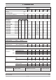
3 - TECHNICAL DATA TABLE 1 Model X Ø 100 ZW Ø 125 Gas oven GN 2/1 Gas oven MAXI Category II2H3+ Construction type A Air necessary for combustion m3/h 8.0 23 16.0 24.0 Nominal thermal power kW 4.0 9.5 7.8 12.0 1.2 3.9 - - kW Hour consumption Minimum thermal power Overall thermal power (gas) AGB 358/WP AGB 359/WP G20 m3/h G25 m3/h G30/G31 kg/h 13.9 kW 1,47 - 1,09 19.4 kW 2,05 - 1,52 AGB 351-360/WP 33.3 kW 3,52 - 2,60 AGB 361/WP 38.
4 - INSTALLATION INSTRUCTIONS 4.1 Safety rules • Only a local gas utility technician is authorized to carry out gas installations and connections. The statutory regulations (applied in Germany VDE, Austria ÖVE, Switzerland SEV, etc.) and connection conditions performed by the gas utility must be strictly observed. • Connection to a power balance system for the installation in a wall is provided for through a connection point. Adhere to current local legal requirements for connection.
4 - ISTRUZIONI PER LA MESSA IN OPERA If the type of gas indicated on the data plate of the appliance does not correspond to the gas which is present, refer to the paragraph "Conversion and adaptation". 4.3.
5 - SET-UP FOR OPERATION Fig. 1 A 3 2 1 4 8 14 5 6 10 7 17 12 22 0 13 9 11 21 5.1.4 Power check with volumetric method Using a gas meter and a stopwatch, you can read the volume of gas output per time unit. The correct volume corresponds to the value "E" expressed in litres/hour (l/h) or litre/minute (l/min). The following formula is used to calculate the value of “E”: Power E= Operating calorific value It is important measure the power when the appliance is in standby status.
5 - SET-UP FOR OPERATION Fig. 2A 18 19 9 15 17 13 3 2 4 11 12 A 14 16 Fig. 2B 19 18 2 15 6 14 3 9 16 Fig.
5 - SET-UP FOR OPERATION the instructions, and hand him this manual. • Remind the user that any structural alterations or any building modification or renovation may affect the combustion air supply, thus requiring a second operation check. 5.1.10 Conversion and adjustment To change over form one kind of gas to another, for example from methane to liquid gas, or to another type of gas, the use of suitable nozzles for the main burner is required, in accordance with the table "TECHNICAL DATA".
5 - SET-UP FOR OPERATION Fig. 3A Fig. 3B 3 2 6 3 6 2 4 1 5 5 2 3 4 AX M 1 7 23 4 the ignition wire and unscrew the screws (15). Insert a new plug. 5.3.4 Gas oven gas valve (Fig. 3A/3B) Loosen the fittings (1,2,3,4 in fig. 3A and 1,2,3 in fig. 3B) which are for the connection for the gas pipe and the thermocouple, remove the coil of the thermostat from its place in the cooking chamber and put in a new piece in the reverse sequence.
6 - INSTRUCTIONS FOR USE 6.1 Safety, cleaning and repair rules any non-compliance with the provisions contained in this manual. • This appliance is used for the preparation of meals at industrial level. Usage and cleaning can be carried only by expert personnel. Maintenance and repair can be carried out only by skilled technical personnel. • These indications must be communicated to all those concerned during internal training.
6 - INSTRUCTIONS FOR USE Fig. 4B 2 1 3 4 5 3 0 0 50 3 100 300 0 15 0 25 200 8 Turn on the switch located up the line from the unit. Press the knob and turn it to the left until the spark position (5). Hold the knob down and at the same time press the piezo ignition button (6) repeatedly. Hold the knob down for 15-20 seconds after the burner lights, which can be observed through the hole in the bottom of the cooking chamber (with the door open). 6.3.
6 - INSTRUCTIONS FOR USE 6.7 Appliance care and frequency of maintenance Attention! When cleaning, carefully avoid washing the appliance with direct water jets or high-pressure water! Cleaning must be performed when the appliance is cold. Thorough daily cleaning of the appliance, after disconnecting it, will keep it in perfect working order and make it last longer. All steel parts should be cleaned with water and a detergent, using a damp cloth; do not use abrasive substances or corroding detergents.
6 - INSTRUCTIONS FOR USE 6.8.3 The 2002/96/EC (WEEE) Directive: information to users This informational note is meant only for owners of equipment marked with the symbol shown in Fig. A on the adhesive label featuring the technical specifications applied on the actual product (the label also giving the serial number).
7 - APPENDIX: ELECTRICAL DIAGRAMS R T C P3 P4 2 5 1 P5 6 P6 7 P1 2 G 1 3 P2 4 RC RG ~ MV RV RS L N A A C R G RC Terminal board Commutator Green indicator light Yellow indicator light Top heating element 063_03 - GAS KITCHENS RG RS RV MV T Grill heating element Bottom heating element Fan heating element Motorized fan Thermostat 03/2006 19 · 22
7 - APPENDIX: ELECTRICAL DIAGRAMS 90101 H1 1 H2 2 3 4 5 6 R1 5 6 2 7 1 3 R2 4 1 B2 P3 P4 P6 2 3 4 5 6 P2 P5 1 2 3 4 B1 mA L1 L 2 L 3 N F2 F1 P1 P2 P3 P4 PE 400 V 3N ~ 8.48 A 1 2 3 4 R1/R2 mA 1 2 3 4 5 6 1 2 3 4 5 6 L1 L 2 L 3 230 V 3 ~ 14.75 A 3 2 1 1 0 B2 2 L1 5 6 7 P3 P4 P5 2 1 P6 3 3 4 mA R1/R2 N 4 P2 230 V ~ 25.7 A Connected power: 5.
7 - APPENDIX: ELECTRICAL DIAGRAMS 90101 v. 4 PE 1 2 3 4 R1/R2 mA 1 2 3 4 5 6 1 2 3 4 5 6 L1 L 2 L 3 230 V 3 ~ 14.75 A mA B1 F1 F2 H1 H2 R1 R2 Terminal board Switch Thermostat Temperature limiter Green indicator light Orange indicator light Upper heating elements Lower heating elements PE 3 2 1 1 0 B2 2 L1 5 6 7 P3 P4 P5 2 1 P6 3 3 4 mA R1/R2 N 4 P2 230 V ~ 25.
WARNING THE MANUFACTURER CANNOT BE HELD RESPONSIBLE FOR ANY INACCURACIES IN THIS BOOKLET DUE TO COPYING OR PRINTING ERRORS. DUE TO ITS POLICY OF CONTINUAL PRODUCT IMPROVEMENT, THE MANUFACTURER RESERVES THE RIGHT TO MAKE ANY CHANGES DEEMED NECESSARY. THE MANUFACTURER CANNOT BE HELD RESPONSIBLE IF THE INSTRUCTIONS CONTAINED IN THIS MANUAL ARE NOT OBSERVED. THIS DOCUMENTATION IS ONLY INTENDED FOR QUALIFIED TECHNICIANS WHO ARE AWARE OF THE RESPECTIVE SAFETY REGULATIONS. WHIRLPOOL EUROPE srl V.