016_03 Installation, operating and maintenance instructions ELECTRIC COOKERS AGB 355/WP AGB 364/WP · AGB 365/WP AGB 366/WP · AGB 367/WP 02/2006
INDEX Models and dimensions page 3 Technical data 5 Installation instructions 6 Installation 6 Legal and technical requisites 6 Installation 6 Wiring 6 Unipotential 6 Using the appliance Ignition 6 6 Cleaning and taking care of the appliance 7 What to do if not using the appliance for a long time 7 What to do if something goes wrong 7 Maintenance 7 WEEE Directive 8 Wiring diagrams Warning 016- 03 - Electric cookers 9-17 18 2
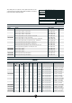
Dimensions AGB 364/WP AGB 365/WP 400 x 900 x 275 Weight approx.52 kg 800 x 900 x 275 Weight approx.96 kg AGB 355/WP 800 x 900 x 275 Weight approx.
Dimensions 0 80 0 270 270 40 900 900 AGB 366/WP AGB 367/WP Weight approx.52 kg Weight approx.
The data plate is located on the rigth hand side of the control panel and contains all the data needed for connecting it up to the mains electricity supply. CAT/KAT GAS/GAZ G30 G20 G25 II2H3B/P P mbar 30 30 20 - SE FI DK II2H3+ P mbar 30 37 G31 20 - IT CH PT II2H3+ P mbar 28 37 20 - ES IE GB P mbar 30 30 - 25 NL P mbar 50 50 20 20 DE TIPO/TYPE II2E+3+ P mbar 28 37 20 25 FR BE MOD. II2H3B/P P mbar 50 50 20 - AT CH ART.
INSTALLATION INSTRUCTIONS efore beginning installation, remove all packaging from the appliance. Some parts are protected with an adhesive film which should be carefully removed. Any remnants of glue should be thoroughly cleaned using suitable substances such as benzine. Under no circumstances should abrasive substances be used. Fit the legs to the appliance. The appliance must be levelled using a spirit level. Slight irregularities can be levelled by adjusting the feet themselves.
Daily cleaning means better performance and a longer useful life. Before starting to clean the appliance, disconnect from the mains.** Remove all the extractable parts from the oven and wash separately. All steel parts should be washed in warm water, using a neutral detergent. Avoid using abrasive or corrosive detergents which could damage the steel. 6 to begin cooking max.
THE 2002/96/EC DIRECTIVE (WEEE): information to users This informational note is meant only for owners of equipment marked with the symbol shown in Fig. A on the adhesive label featuring the technical specifications applied on the actual product (the label also giving the serial number).
Wiring diagrams AGB 364/WP R2 N2 N2 N1 N1 N3 2 R2 R2 N3 3 1 4 2 3 1 4 6 3000 w 5 2250 w 4 1500 w 3 750 w 2 500 w 1 300 w 0 B1 H1 H1 5 B1 P3 2 1 3 P1 4 P2 5 B1 P3 2 P1 1 3 5 2 1 3 3 4 P3 P1 P2 4 P2 1 2 3 230 V 3~ 26,7 A 1 mA 1 2 400 V 3N~ 15,3 A Line input terminal board Hotplate commutator Pilot lamp Hotplate 016- 03 - Electric cookers 3 3 L1 L2 N mA B1 H1 R2 2 9 230 V ~ 26,7 A
Wiring diagrams AGB 365/WP R2 R2 R2 R1 N2 N2 N2 N2 N1 N1 N3 2 3 1 2 4 H1 P3 2 1 3 P1 4 3 1 2 4 N3 3 1 2 4 H1 5 B1 P2 N1 N3 H1 5 B1 N1 N3 P3 2 P1 1 3 4 4 H1 5 B1 P2 3 1 P3 2 P1 1 3 4 5 B1 P2 P3 2 1 3 P1 4 P2 R1 R2 6 4000 w 3000 w 5 2500 w 2250 w 4 1500 w 1500 w 3 1000 w 750 w 2 600 w 500 w 1 430 w 300 w 0 mA 1 2 3 4 5 B1 6 5 2 1 3 3 4 P3 P1 P2 400 V 3N~ 22,9 A L1 L 2 L 3 N 1 2 3 4 5 6 m A L1 L 2 L 3 230 V 3~ 38,2 A
016- 03 - Electric cookers mA B1 H1 R1-2 Bôite à bornes Commutateur plaque Lampe témoin Plaque de cuisson P3 5 B1 H1 P1 2 mA 2 N1 4 H1 2 2 N3 11 3 4 L1 L 2 L 3 N 2 P2 1 3 4 5 6 P3 5 B1 P1 P2 1 3 3 1 N2 N2 3 1 1 N3 R2 R1 4 4 N1 P1 2 P2 1 3 3 1 4 4 N1 400 V 3N~ 26,7 A P3 5 B1 H1 2 N3 N2 R2 P3 5 B1 H1 2 2 4 3 P2 1 3 3 1 5 2 6 m A P3 5 B1 H1 230 V 3~ 53,5 A 4 4 N1 L1 L 2 L 3 1 P1 2 N3 N2 R2 P1 2 N3 P2 1 3 3 1 N2 R2 4 P1
016- 03 - Electric cookers mA B1 B2 B3 F1 H1 H2 R1 R2-3 F2 Bôite à bornes Commutateur plaque Interrupteur EGO Commutateur EGO Thermostat EGO Lampe témoin Lampe témoin (tension) Plaque de cuisson Résistance du four Thermostat de sureté.
016- 03 - Electric cookers mA B1 B2 B3 F1 H1 H2 R1 R2-3 F2 P1 2 N1 6 H1 2 2 N3 P2 1 3 3 1 5 4 4 B2 13 2 H1 3 4 P1 P2 1 3 4 H2 4 N1 400 V 3N AC P1 P2 P3 P4 1 P3 5 B1 3 1 N2 N2 Line input terminal board Hotplate commutator Switch EGO Switch EGO Thermostat EGO mA 1 2 3 4 Pilot lamp Pilot lamp (voltage) Hotplate L1 L 2 L 3 N Oven resistance Safety thermostat.
Wiring diagrams AGB 366/WP R2 R1 2 2 S S H H H2 H2 B1 B1 50 55 50 55 P1 P1 H1 H1 2 4 40 S2 S1 S2 1 2 3 4 L1 L 2 L 3 N Line arrival terminal board Double power plate energy regulator Pilot lamp Residual heat pilot lamp 1000/2500 W cooking plate 1500/3400 W cooking plate 016- 03 - Electric cookers P2 40 mA mA B1 H1 H2 R1 R2 2 4 P2 14 5 6 PE 400 V 3N S1
Wiring diagrams AGB 366/WP R2 R1 2 2 S S H H H2 H2 B1 B1 50 55 50 55 P1 P1 H1 H1 2 4 40 S2 S1 S2 1 2 3 4 L1 L 2 L 3 Line arrival terminal board Double power plate energy regulator Pilot lamp Residual heat pilot lamp 1000/2500 W cooking plate 1500/3400 W cooking plate 016- 03 - Electric cookers P2 40 mA mA B1 H1 H2 R1 R2 2 4 P2 15 5 6 PE 230V 3 S1
Wiring diagrams AGB 367/WP R2ps 2 R1pd 2 S S R1as H R2ad H 2 2 S S H H B1 B1 S2 mA 1 2 3 4 L1 L 2 L 3 N 5 6 2 4 P2 40 S1 S2 400 V 3N PE Line arrival terminal board Double power plate energy regulator Pilot lamp Residual heat pilot lamp 1500/3400 W cooking plate rear left 1000/2500 W cooking plate front left 1500/3400 W cooking plate front right 1000/2500 W cooking plate rear right 016- 03 - Electric cookers P1 H1 P2 40 S1 50 55 P1 2 4 P2 B1 50 55 H1 2 mA B1 H1 H
Wiring diagrams AGB 367/WP R2ps 2 R1pd 2 S S R1as H R2ad H 2 2 S S H H B1 B1 S1 S2 1 2 3 L1 L 2 L 3 4 5 6 2 4 P2 40 S1 S2 230V 3 PE Line arrival terminal board Double power plate energy regulator Pilot lamp Residual heat pilot lamp 1500/3400 W cooking plate rear left 1000/2500 W cooking plate front left 1500/3400 W cooking plate front right 1000/2500 W cooking plate rear right 016- 03 - Electric cookers P1 H1 P2 40 mA 50 55 P1 2 4 P2 B1 50 55 H1 2 mA B1 H1 H2 R2
WARNING THE MANUFACTURER CANNOT BE HELD RESPONSIBLE FOR ANY INACCURACIES IN THIS BOOKLET DUE TO COPYING OR PRINTING ERRORS. DUE TO ITS POLICY OF CONTINUAL PRODUCT IMPROVEMENT, THE MANUFACTURER RESERVES THE RIGHT TO MAKE ANY CHANGES DEEMED NECESSARY. THE MANUFACTURER CANNOT BE HELD RESPONSIBLE IF THE INSTRUCTIONS CONTAINED IN THIS MANUAL ARE NOT OBSERVED. WHIRLPOOL EUROPE srl V.