054_03 Installation, operating and maintenance instructions GAS BAIN-MARIE AGB 452/WP 11/2005
INDEX Dimensions Data of appliances Technical data Operating instructions page Adjusting the primary air 3 4 4-5 6 Construction, equipment installed and safety devices page 9 Maintenance 9 Replacing parts 9 Valve 9 Safety termostat 9 Burner 9 Thermocouple 9 Ignition plug 9 6 Assembly 6 Using the appliance 11 Location 6 Preparation for use 11 Legal and technical requisites 6 Filling the tank 11 6 Turning on and off 11 Installation procedure 7 Lighting the main 11 Gas
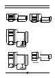
15 1/2"GC 510 300 510 300 655 1/2"GC 142 15 1/2"GC 400 700 875 1085 1085 400 25 142 1/2"GC 1/2"GC 1/2"GC 25 430 430 Dimension 1/2"GC 35 25 155 1/2"GC 400 1/2"GC 75 208 270 480 700 875 1085 3/4"GC 400 AGB 452/WP 25 400 3/4"GC 3/4"GC 310 900 054- 03 - Gas Bain-marie 3 900
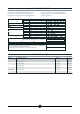
2 - DATA OF APPLIANCES The instructions contained in this manual apply to our gas bain-marie in the II2H3+ category (see table on page 5). The data plate is located on the front of the appliance and on the control panel. It contains all necessary reference data such as the name of the manufacturer, input pressure, gas type setting, etc.
TABLE 1 AGB 452/WP Model Category II2H3+ Construction type A Air necessary for combustion m3/h 5 8 Nominal thermal power kW 2.4 4.0 Minimum thermal power kW - - Connection pressure Methane gas 2H G20 20 mbar Liquid gas 3+ G30/G31 28/37 mbar Gas connection values Methane gas 2H (HuB = 9.45 kWh/m3) m3/h 0.254 0.423 Liquid gas 3+ (HuB = 12.87 kWh/kg) kg/h 0.188 0.
OPERATING INSTRUCTIONS Construction, equipment installed Legal and technical requisites and safety devices During assembly, the following legal and technical Robust steel frame, with 4 legs (adjustable in height). 18/10 chrome-nickel steel outer panelling and tanks. The water is heated by burners in stainless steel (2 per tank), built to withstand thermomechanical stress. The pilot burner has stable injectors. The combustion chamber and flues are made of electro-galvanised steel sheeting.
Installation procedure Gas venting To level the appliance correctly, adjust the height of the four legs. These appliances are A construction type, thus no gas venting is required. For advice on ventilating the premises where the appliance is installed, observe current regulations. Gas connection The R 3/4” gas off-take on the appliance can either be permanently fixed to the mains or made detachable using a standard gas tap.
2 2 1 3 19 16 21 17 WARNING It is not possible to adjust nominal capacity in advance. Checking power rating when using LP gas Check that the type of nozzles used match manufacturer's specifications. Check that the pressure reducer installed on the appliance has an outlet pressure in compliance with paragraph "Testing the power rating", page 7(see data plate or measure the pressure).
1 40 30 31 39 28 29 26 REPLACING PARTS Adjusting the primary air To adjust the primary air according to the data in table (1), the fixing screw (99 - Fig. 1) must be loosened. MAINTENANCE All parts must be replaced by authorised technicians only! To replace the following parts, remove the control panel (after unscrewing its fixing screws). It is advisable to empty the tank. Attention! Valve (1 - Fig. 2) Before carrying out any maintenance or repair work, disconnect the appliance from the mains.
3 AGB 452/WP 10 12 10 13 6 34 37 38 36 35 054- 03 - Gas Bain-marie 10
USING THE APPLIANCE Warning! - The appliance should never be left unattended when in use! - Water should be added if the level drops below the minimum level indicated on the tank. - The appliance should never be used dry. Lighting the main burner of the tank To ligth the main burner, turn the knob to the position required.
Floor-standing version Check that the standard container is available for emptying procedure. The container should be placed correctly on the proper guides and fully inserted. It is advisable to filter frying oil and fat daily and to change completely when necessary. Open the drainage tap; when the tank is empty, close the tap before removing the container.
WARNING DUE TO ITS POLICY OF CONTINUAL PRODUCT IMPROVEMENT, THE MANUFACTURER RESERVES THE RIGHT TO MAKE ANY CHANGES DEEMED NECESSARY. THE MANUFACTURER CANNOT BE HELD RESPONSIBLE IF THE INSTRUCTIONS CONTAINED IN THIS MANUAL ARE NOT OBSERVED. WHIRLPOOL EUROPE srl V.