
Instruction for Use


054
-
03 - Gas Bain-marie
7
Installation procedure
To level the appliance correctly, adjust the height of
the four legs.
Gas connection
The R 3/4” gas off-take on the appliance can either
be permanently fixed to the mains or made detacha-
ble using a standard gas tap.
If flexible ducts are used, these should be made of stain-
less steel and should comply with current regulations.
After completing connection, check for leaks using a
special leak-detector spray.
Gas venting
These appliances are A construction type, thus no
gas venting is required.
For advice on ventilating the premises where the
appliance is installed, observe current regulations.
COMMISSIONING THE APPLIANCE
Before commissioning the appliance
Before commissioning the appliance, remove the
protective wrapping.
Thoroughly clean the work-surface and the outside
of the appliance using lukewarm water and deter-
gent.
With a damp cloth eliminate all traces of the rust-
proofing applied in the workshop then dry with a
clean cloth.
Start-up
Before starting the appliance up, check that its spe-
cifications (category and type of gas used) match
those of the family and group of the gas available
locally.
If not, adapt the appliance to the gas family or
group required (see paragraph “Running the ap-
pliance on other types of gas”, page 8).
To start the appliance up, see the instructions for
regular use.
Testing the power rating
Use the specific nozzles for the rated output (see
table 1 in assembly instructions).
Working tolerances for the capacity obtained accor-
ding to the nozzles used, are as follows:
- tolerances within the following fields of input
pressure:
- from 15 to 22.5 mbar for gases of the second family;
- from 25 to 45 mbar for gases of the third family
(propane).
The appliance will not work outside the above pres-
sure thresholds.
If you wish to check the nominal capacity further,
you may do so using a gas meter according to the
so-called ”volumetric method”.
As a rule, however, it is sufficient to check that the
correct nozzles are being used.
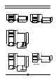
Checking input pressure (Fig. 2)
Input pressure should be measured using a gauge
(e.g. a gooseneck pipe, min. resolution 0.1 mbar).
Remove screw (19) from the pressure socket and
connect it to the tube on the gauge; after measu-
ring, the screw should be retightened absolutely
airtight (19).
Checking power rating using the
volumetric method
Using a gas meter and a chronometer, you can
read the volume of gas output per time unit.
The correct volume will be the value of “E” expres-
sed in litres per hour (It/hr) or litres per minute
(It/min).
The following formula is used to calculate the value
of “E”:
Capacity should only be measured when the ap-
pliance is at a standstill.
The heat value can be obtained from your local Gas
Board.
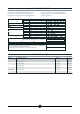
To obtain the nominal capacity in relation to the no-
minal pressure, consult table (1) (Gas Flow
Setting).
Capacity
Heat value
E =