049_03 Instructions for installation, use and maintenance GAS FRYERS APPLIANCES WITH MECHANICAL VALVE AGB 595/WP • AGB 596/WP AGB 517/WP • AGB 518/WP AGB 512/WP • AGB 513/WP 11/2005
INDEX Dimensions page 3 Running the appliance on other types of gas Data of appliances Technical data Operating instructions 4 4-5 page 8 Replacing the main burner nozzle 8 Adjusting the pilot burner 9 Adjusting the primary air 9 Maintenance 9 6 Replacing parts 9 Construction, equipment installed Valve 9 6 Safety termostat 9 Assembly 6 Burner 9 Location 6 Thermocouple 9 Legal and technical requisites 6 Ignition plug 9 and safety devices Installation 6 Installation proced
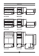
1/2"GC 15 800 15 1/2"GC 400 1/2"GC 25 300 430 Dimensions 655 AGB 10GM 595/WP SKF 1/2"GC 15 800 15 1/2"GC 400 700 AGB 512/WP 875 1085 AGB 513/WP 1/2"GC 25 300 510 AGB 596/WP 1/2"GC 800 25 25 400 1/2"GC 1/2"GC 700 AGB 518/WP 049- 03 - Gas fryers AGB 517/WP 3 208
2 - CHARACTERISTICS OF THE APPLIANCES control panel. It contains all necessary reference data such as the name of the manufacturer, input pressure, gas type setting, etc. The instructions contained in this manual apply to our gas fryers in the II2H3+ category (see table on page 5).
TABLE 1 Model AGB 595/WP AGB 596/WP AGB 517/WP AGB 518/WP AGB 512/WP AGB 513/WP Category II2H3+ Construction type A Air necessary for combustion m3/h 14 28 Nominal thermal power kW 6.9 13.8 Minimum thermal power kW - - Overall thermal power (gas) AGB 595/WP 6.9 kW AGB 517/WP 6.9 kW AGB 512/WP 6.9 kW AGB 596/WP 13.8 kW AGB 518/WP 13.8 kW AGB 513/WP 13.
OPERATING INSTRUCTIONS Construction, equipment installed Attention! and safety devices When installing Robust steel frame, with 4 legs (adjustable in height). 18/10 chrome-nickel steel outer panelling and tanks. The oil is heated by burners in stainless steel (2 per tank), built to withstand thermomechanical stress. The pilot burner has has adjustable injectors. The combustion chamber and flues are made of electro-galvanised steel sheeting.
Installation procedure Gas venting To level the appliance correctly, adjust the height of the four legs. These appliances are A construction type, thus no gas venting is required. For advice on ventilating the premises where the appliance is installed, observe current regulations. Gas connection The R 1/2” gas off-take on the appliance can either be permanently fixed to the mains or made detachable using a standard gas tap.
2 2 1 3 19 16 21 17 The heat value can be obtained from your local Gas Board. To obtain the nominal capacity in relation to the nominal pressure, consult table (1) (Gas Flow Setting). WARNING It is not possible to adjust nominal capacity in advance. Checking power rating when using LP gas Check that the type of nozzles used match manufacturer's specifications.
Adjusting the pilot burner (Fig. 1) REPLACING PARTS To get at the pilot burner, remove the control panel (as previously described). Unscrew nut (34) and using a screwdriver adjust the by-pass. For use with LPG, the adjusting screw must be fully screwed down. Tighten the nut, making sure the gasket has been inserted. All parts must be replaced by authorised technicians only! To replace the following parts, remove the control panel (after unscrewing its fixing screws). It is advisable to empty the tank.
3 AGB 518/WP AGB 517/WP 11 11 10 10 13 13 10 11 13 12 12 AGB 595/WP AGB 512/WP AGB 596/WP AGB 513/WP 11 11 10 10 13 13 10 11 13 12 12 049- 03 - Gas fryers 10
USING THE APPLIANCE Warning! Lighting the main burner of the tank - Beware of inexpert handling! - Old and dirty oil or frying fat can represent a real fire hazard; make sure only new oil or frying fat are used each time you start frying. - The food you intend to fry should always be dry; wet food causes the oil to foam and overflow. - Frying excessively large quantities of food at a time also causes the oil to foam; never exceed 0,8 kg.
Floor-standing version Check that the standard container is available for emptying procedure. The container should be placed correctly on the proper guides and fully inserted. It is advisable to filter frying oil and fat daily and to change completely when necessary. Open the drainage tap; when the tank is empty, close the tap before removing the container.
WARNING DUE TO ITS POLICY OF CONTINUAL PRODUCT IMPROVEMENT, THE MANUFACTURER RESERVES THE RIGHT TO MAKE ANY CHANGES DEEMED NECESSARY. THE MANUFACTURER CANNOT BE HELD RESPONSIBLE IF THE INSTRUCTIONS CONTAINED IN THIS MANUAL ARE NOT OBSERVED. WHIRLPOOL EUROPE srl V.