005_03 06/2007 Instructions for installation, use and maintenance ELECTRIC FRYER AGB AGB AGB AGB AGB 597/WP · AGB 521/WP 515/WP · AGB 598/WP 523/WP · AGB 516/WP 522/WP · AGB 514/WP 524/WP · AGB 525/WP
INDEX Models and dimensions page 3 Cleaning and taking care of the appliance Technical data Installation instructions 4 5 a long time 6 What to do if something goes wrong 6 5 Legal and technical requisites 5 Maintenance Installation 5 Wiring 5 Unipotential 5 Wiring diagrams 5 WEEE Directive Warning Using the appliance 6 Ignition 6 Emptying the bath 6 005- 03 - Electric fryer 6 What to do if not using the appliance for Installation Start-up page 2 6 7 8-12 13
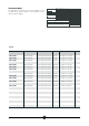
Dimensions E C B E D B C D A AGB 514/WP 400 x 650 x 270 400 x 700 x 510 Weight approx. 21 kg Weight approx. 21 kg A B C D E B E C D A C B E D A C B E D A AGB 597/WP AGB 515/WP AGB 598/WP AGB 516/WP 400 x 650 x 270 Weight approx. 21 kg 600 x 650 x 270 Weight approx. 33 kg 400 x 700 x 510 Weight approx. 21 kg 600 x 700 x 510 Weight approx. 33 kg AGB 522/WP AGB 521/WP AGB 523/WP 400 x 700 x 875 Weight approx. 51 kg 400 x 700 x 875 Weight approx. 51 kg 600 x 700 x 875 Weight approx.
Technical data CAT/KAT II2H3B/P P mbar 30 30 20 - SE FI DK The data plate is located on the front of the appliance and contains all the data needed for connecting it up to the mains electricity supply. II2H3+ P mbar 30 37 20 - IT CH PT II2H3+ P mbar 28 37 20 - ES IE GB GAS/GAZ G30 G31 G20 G25 II2L3B/P P mbar 30 30 - 25 NL II2ELL3B/P P mbar 50 50 20 20 DE II2E+3+ P mbar 28 37 20 25 FR BE MOD. II2H3B/P P mbar 50 50 20 - AT CH ART.
INSTALLATION INSTRUCTIONS Before beginning installation, remove all packaging from the appliance. Some parts are protected with an adhesive film which should be carefully removed. Any remnants of glue should be thoroughly cleaned using suitable substances such as benzine. Under no circumstances should abrasive substances be used. Fit the legs to the appliance; the appliance must be levelled using a spirit level. Slight irregularities can be levelled by adjusting the feet themselves.
USING THE APPLIANCE Warning! - Beware of inexpert handling! - Old and dirty oil or frying fat can represent a real fire hazard; make sure only new oil or frying fat are used each time you start frying. - The food you intend to fry should always be dry; wet food causes the oil to foam and overflow. - Frying excessively large quantities of food at a time also causes the oil to foam; never exceed 1.5 kg.
THE 2002/96/EC DIRECTIVE (WEEE): information to users This informational note is meant only for owners of equipment marked with the symbol shown in Fig. A on the adhesive label featuring the technical specifications applied on the actual product (the label also giving the serial number).
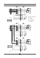
Wiring diagrams H2 H1 F1 mC L1 1 L2 2 L3 N 3 4 5 1 2 11 12 3 4 21 22 5 6 31 32 13 14 L3 L2 R L1 N A2 A1 C1 mA 400 V 3N P4 4 P3 3 P2 2 P1 1 AGB 597/WP AGB 521/WP AGB 515/WP B2 F2 B1 mA mC B1 B2 C1 F1 F2 H1 H2 R Line input terminal board Commutating terminal board Switch Microswitch Contactor Working thermostat Safety thermostat Green pilot lamp Orange pilot lamp Resistance H2 H1 F1 mC L1 1 L2 2 L3 N 3 4 5 1 2 11 12 3 4 21 22 5 6 31 32 13 14 L3 L2
Wiring diagrams H2 H1 mC F1 N L1 1 L2 2 L3 3 1 2 11 12 3 4 21 22 5 6 31 32 L3 L2 R L1 4 5 A2 A1 C1 mA P4 230 V 3 AGB 597/WP AGB 521/WP AGB 515/WP 4 P3 3 P2 2 P1 1 B2 F2 B1 mA mC B1 B2 C1 F1 F2 H1 H2 R Line input terminal board Commutating terminal board Switch Microswitch Contactor Working thermostat Safety thermostat Green pilot lamp Orange pilot lamp Resistance H2 H1 mC F1 N L1 1 L2 2 L3 3 1 2 11 12 3 4 21 22 5 6 31 32 P4 4 P3 3 P2 2 P1
Wiring diagrams AGB 522/WP AGB 514/WP R1 R1 22 23 21 22 23 21 A1 A1 C1 C1 A2 11 12 13 T2 A2 11 12 13 T3 B2 B2 T1 T1 H2 H2 H1 H1 1 1 2 2 B1 B1 P1 P2 P1 P2 mA 1 2 3 4 L1 L 2 L 3 N 5 6 T3 PE 400V 3N mA 1 2 3 L1 L 2 L 3 4 5 6 PE 230 V 3 mA B1 B2 T1 T2 T3 C1/C2 R1 H1 H2 005- 03 - Electric fryer 10 Line input terminal board Switch Microswitch Thermostat Safety thermostat Safety thermostat Contactor Resistance Green pilot lamp Orange pilot lamp
Wiring diagrams AGB 524/WP 2 4 6 R 1 mC 1 3 2 5 3 4 m C2 B2 C1 F2 H2 H1 B1 mA 1 2 3 4 5 L1 L 2 L 3 N F1 6 PE 400V 3N 6 mA 1 2 3 4 5 2 PE 230V 3 mA mC B1 B2 C1 C2 F1 F2 H1 H2 R Line input terminal board Commutating terminal board Switch Microswitch Safety contactor Adjusting contactor Adjusting thermostat Safety thermostat Green pilot lamp Orange pilot lamp Resistance 005- 03 - Electric fryer 3 5 6 mC L1 L 2 L 3 1 4 11 1 2 3 4
Wiring diagrams AGB 525/WP 2 4 2 6 4 6 R R 1 mC 1 3 2 1 5 3 4 m mC 1 3 2 5 3 4 m C2 C2 B2 B2 C1 C1 F2 H2 H1 B1 mA 1 2 3 4 L1 L 2 L 3 N 5 H1 B1 F1 6 PE 400V 3N 6 mA 1 2 3 4 5 L1 L 2 L 3 4 12 1 3 F1 5 6 PE Line input terminal board Commutating terminal board Switch Microswitch Safety contactor Adjusting contactor Adjusting thermostat Safety thermostat Green pilot lamp Orange pilot lamp Resistance 005- 03 - Electric fryer 2 mC 230V 3 mA mC B1 B
WARNING DUE TO ITS POLICY OF CONTINUAL PRODUCT IMPROVEMENT, THE MANUFACTURER RESERVES THE RIGHT TO MAKE ANY CHANGES DEEMED NECESSARY. THE MANUFACTURER CANNOT BE HELD RESPONSIBLE IF THE INSTRUCTIONS CONTAINED IN THIS MANUAL ARE NOT OBSERVED. THIS DOCUMENTATION IS ONLY INTENDED FOR QUALIFIED TECHNICIANS WHO ARE AWARE OF THE RESPECTIVE SAFETY REGULATIONS. WHIRLPOOL EUROPE srl V.