ELECTRIC OVEN AGS 646/WP Installation, user and maintenance instruction Instruction AGS 646-WP- rev9 english ed.
CONTENTS SCHEMATIC REPRESENTATION GENERAL INFORMATION AND SAFETY INSTRUCTIONS General safety instructions Appliance specifications Legal requirements, technical regulations and directives Special conditions required for the place of installation Technical data Design characteristics POSITIONING, INSTALLATION AND MAINTENANCE Positioning 2002/96/EC (WEEE) directive Installation Electrical connection and equipotential bonding Commissioning test and putting into service Maintenance of the appliance USING AND C
SCHEMATIC REPRESENTATION GENERAL INFORMATION AND SAFETY INSTRUCTIONS GENERAL SAFETY INSTRUCTIONS - Carefully read the safety instructions in this booklet, as they will give you important information about how to install, maintain, and use the appliance safely. - Keep this booklet in a safe place. - These appliances are intended for professional use in a restaurant environment, and must therefore be used only by trained staff. - When in operation, the appliance should not be left unsupervised.
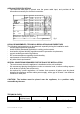
APPLIANCE SPECIFICATIONS - The technical data plate is placed near the power cable input, and provides all the information necessary for electrical connection. CAT/KAT GAS/GAZ G30 G31 G20 G25 II2H3B/P 1035° II2H3+ II2H3+ 0049 II2L3B/P II2ELL3B/P TIPO / TYPE II2E+3+ MOD. II2H3B/P I2E ART.
DESIGN CHARACTERISTICS - Load-bearing structure of stainless steel with 4 feet adjustable in height. - Digital controls: start-stop / temperature / timer / interior light – heating is provided by two shielded resistors equipped with a motor-fan. - Temperature is controlled electronically, and goes ahead from room temperature to 450°C. - Safety thermostat to protect against failure of the temperature control sensors. - Recirculating fan. - Orange LED is lit when the appliance is in use.
Producers and importers fulfil their responsibility for environmentally compatible recycling, treatment and disposal both directly and by joining a collective scheme. - Place the oven on a surface able to support the weight, with the left side at least 50 cm from the wall or from other appliances. In general, we recommend leaving a gap of at least 10 cm around all the other sides for cooling, steam evacuation and for maintenance/repair work by technical support.
- Check that the earthing system is working effectively. The appliance must also be included in an equipotential bonding system. Connection is through the terminal (marked with the international symbol) provided on the back of the oven, using a cable of nominal section less than 4 mm2. This connection is applied between all installed appliances and the short-circuit stable earthing system.
- In the event of a malfunction in the appliance, disconnect all power supplies and call technical support. If a fault occurs repeatedly, technical support must be called. USER INSTRUCTIONS - Before switching on and using the appliance for the first time, it is essential to carefully clean the oven interior and any accessories that come into contact with food. CONTROL PANEL fig.2 SWITCHING ON (fig.2) - Operate the main switch upstream of the appliance.
- - When point symbol (4) is lit, it indicates that the time is set in hours/minutes; when off, the setting is in minutes/seconds. To indicate that the timer is running, point symbol (5) flashes at the rate of one flash per second. To set the time, use buttons (7), (+) to increase and (-) to decrease.
COOKING Pizza: - Insert the cooking cylinders before switching the oven on. - When the oven reaches the set temperature, (400°C-420°C down and 380°C-400°C up), the oven is ready for cooking. Working temperature is reached in about 4 minutes. Meantime, you can spread out the pasta, place it on the grate, season it and insert in the oven. It is cooked in about 1’ 40”. When cooking is complete, take out the grate using the shovel supplied, and slide the pizza onto the board.
PRECAUTIONS IF NOT USING FOR LONG PERIODS - If not using for long periods, clean the appliance thoroughly and remove any residues, then dry perfectly. We recommend leaving the door slightly open to allow air to circulate inside the oven and preserve the lining. You can use the protective substances commonly available on the market to protect the stainless steel parts. Disconnect the appliance from the power supplies. The room should be kept dry and well ventilated.
RESERVED FOR TECHNICAL SUPPORT SERVICE CONNECTIONS Connector Description CN2 TTL serial port for use by Technical Support for updating the software CN9 CN1 Notes Requires a suitable adaptor for connection to a Personal Computer Activates Test mode when Jumper for selecting Test mode inserted Factory programming connector Reserved for the manufacturer THERMOCOUPLE CONNECTIONS Terminal Name Description Notes CN3-1 S+ Positive wire upper thermocouple J Type or K Type CN3-2 CN4-1 CN4-2 SI+
POWER CONNECTIONS Terminal Name CN5-1 RS1 CN5-2 RS2 CN5-3 RI1 CN6-1 RI2 CN6-2 V12 CN6-3 V3 CN7-1 LMP CN7-2 CN7-3 CN8-1 UMD -L CN8-2 N CN8-3 PE Description Notes Common contact Controlo relay for upper resistor Normally Open contact Control relay for upper resistor Common contact control relay for lower resistor Normally Open contact Control relay for lower resistor Control relay NO contact Upper and lower fans [RL3] Control relay NO contact for air recirculation fan [RL4] Control re
- Press button 12 (fig. 2) for the interior light (SW11) to light up all parts of the display. Remove jumper CN9 to exit AUTO-TEST mode and automatically go into analog channel display mode. See also “Resetting the thermocouple offset”. To go back to normal working mode, press the timer START/STOP button.
NOTICE: The manufacturer cannot accept liability for any inaccuracies that may occur in this booklet due to transcription or printing errors. They also reserve the right to make any modifications to the product that they consider useful or necessary, without changing the essential specifications. The manufacturer will not accept any liability whatsoever if the regulations and instructions described in this manual are not strictly observed. WHIRLPOOL EUROPE S.r.l. V.