
Instruction for Use


GB8
INSTALLATION - PRELIMINARY ASSEMBLY INSTRUCTIONS
INSTALLATION - ASSEMBLY INSTRUCTIONS
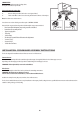
The instructions below, to be carried out in the order in which they are numbered, refer to the gures (with the same step numbers) given on the last pages of this
manual.
1. Position the wall unit shelf at a height of 14 cm from the bottom
2-3-4. Position the drilling template on the bottom of the shelf, drill the 4 Ø 5mm side holes and prepare the central opening for the air vent
5. Fit the check valve for fumes to the hood’s fumes outlet
6. Feed through the power supply cable and secure the cable clamp (using n.1 screw 3.5x9.5)
7. For the upper outlet: drill the top of the wall unit, taking into account the position of the outlet hole
8. For rear outlet: drill the back of the wall unit at the desired height
9. Secure the hood to the wall unit using the 4 screws 4.2x35
10. Open the steam deector and remove the metal grease lters
11. Adjust the slideout stroke of the deector by installing the two brackets provided; x them using the 2 screws 3.5x9.5
12-13. Fit ducting for the venting of fumes, connecting it to the connector ring (for the Filter version, a small section of ducting that reaches the top of the wall
unit will suce)
NB: the ducting is not included in the pack and must be purchased separately
14. For lter version only: t the carbon lter (refer to instructions in the section MAINTENANCE-Carbon Filter)
15. Ret the metal grease lters
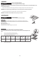
Wall unit interior 600 mm min
Wall unit interior 900 mm min
centre line
65 cm (gas or combi cookers)
50 cm (electric cookers)
Adjacent wall units
Adjacent wall units
hob surface
This type of hood must be installed inside a wall unit or similar support.