GB User and maintenance manual
IMPORTANT SAFETY INSTRUCTIONS These instructions shall also be available on website: www.whirlpool.eu. YOUR SAFETY AND THAT OF OTHERS IS HIGHLY IMPORTANT. This manual and the appliance itself provide important safety warnings, to be read and observed at all times. This is the attention symbol, pertaining to safety, which alerts users to potential risks to themselves and others.
• When drilling through a wall or the ceiling, pay attention not to damage electric connections and/or pipes. • The ventilation ducts must always discharge to the outside. • Exhaust air must not be vented through a flue used for removal of fumes produced by appliances burning gas or other fuels, but must have a separate outlet. All national regulations governing extraction of fumes must be observed.
Declaration of conformity • This appliance has been designed, manufactured and marketed in compliance with: - safety objectives of the “Low Voltage” Directive 2014/35/EU; - the ecodesign requirements of european regulations n. 65/2014, and n. 66/2014 in conformity to the european standard EN 61591; - the protection requirements of Directive “EMC” 2014/30/EU. Electrical safety of the appliance can only be guaranteed if it is correctly connected to an approved earthing system.
TROUBLESHOOTING GUIDE The appliance does not work: • Check for the presence of mains electrical power and if the appliance is connected to the electrical supply; • Turn off the appliance and restart it to see if the fault persists. The hood's suction level is not sufficient: • Check the suction speed and adjust as necessary; • Check that the filters are clean; • Check the air vents for any obstructions.
MAINTENANCE WARNING: - use protective gloves. - disconnect the appliance from the power supply. GREASE FILTERS The metal grease filter has an unlimited life and should be cleaned once a month by hand or in a dishwasher at low temperature and with a short cycle. Cleaning in a dishwasher may cause discoloring of the grease filter, but its filtering efficiency is unaffected. Pull out the steam deflector. Pull out the handle to remove the filter.
MATERIAL SUPPLIED Remove all the components from the packets. Check that all the components are included. • Hood assembled with motor, lamps and grease filters installed. • Instructions for assembly and use • 1 power supply cable • 1 allen key • 1 cable clamp • 2 brackets for steam deflector slideout stroke adjustment • 3 screws 3.5x9.5 • 4 screws 4.
INSTALLATION - ASSEMBLY INSTRUCTIONS The instructions below, to be carried out in the order in which they are numbered, refer to the figures (with the same step numbers) given on the last pages of this manual. 1. Position the wall unit shelf at a height of 14 cm from the bottom 2-3-4. Position the drilling template on the bottom of the shelf, drill the 4 Ø 5mm side holes and prepare the central opening for the air vent 5. Fit the check valve for fumes to the hood’s fumes outlet 6.
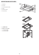
DESCRIPTION AND USE OF HOOD 1. Control panel. 2. Grease filter. 3. Grease filter spring release handles. 4. Lighting 5. Pull-out steam deflector 6. Extractor unit body. a. Light ON/OFF switch b. OFF/speed 1 selector switch c. Speed 2 selector switch c.
1
2 3 4
5 6
Ø 130mm 113.
4x Ø 4,2x35 9
10 2x Ø 3,5x9,5 OK! 11
12 13
14 15
Printed in Italy 09/2016 400010907692 EN