32602007GB.
32602007GB.fm Page 27 Thursday, February 1, 2007 5:16 PM PRECAUTIONS FOR USE Warning: • Make sure to insert the power plug securely. Insecure insertion of the plug may cause electrocution or fire. • Never unplug the machine while running. • Do not damage the cord or use an unapproved cord. • Do not plug other electric appliances into the same socket or use extension cords. • Never operate the air conditioner with wet hands. • Do not pull the plug out by the cord.
2602007GB.fm Page 28 Thursday, February 1, 2007 5:16 PM Warning: • Do not cut or damage the power cords and control lines. Any damaged power cords and signal control lines of the air conditioner must be replaced by qualified technicians with special cords. • Persistent abnormality indicates that the air conditioner may be damaged with the consequent risk of electric shock or fire. This may cause an electric shock. • To prevent fire always use a special power supply circuit.
32602007GB.fm Page 29 Thursday, February 1, 2007 5:16 PM SPECIFICATIONS AND TECHNICAL DATA (DEPENDING ON THE MODEL) Model AMD060 AMD061 Functions Cooling capacity (W) Cool/Heat 2667x2 Cool/Heat 2667+3517 Heating capacity (W) 2696x2 2696+3575 Rated voltage 220-240V~ Rated frequency Cooling/Heating rated power (W) 1656/1595 50Hz 2053/1960 Energy-efficiency ratio 3.22/3.38 3.01/3.20 Recycling air volume (CFM) Refrigerant and weight 265/265 R410A (0.96x2)Kg 265/295 R410A (0.9+1.
32602007GB.fm Page 30 Thursday, February 1, 2007 5:16 PM INSTRUCTIONS FOR USE The Principle and Special Functions of Cooling Mode Principle: The air conditioner absorbs heat from indoor air and discharges it outdoors, thus lowering the indoor room temperature. Cooling capacity decreases with a rise in outdoor temperatures. Anti-freeze Function: Frost may appear on the surface of the indoor heat exchanger if the air conditioner is running under low-temperature cooling mode.
32602007GB.fm Page 31 Thursday, February 1, 2007 5:16 PM DESCRIPTION OF AIR CONDITIONER COMPONENTS Indoor Unit AMD 060 AMD 061 Air in A unit Air out Air in B unit Air outlet 1. 2. 3. 4. 5. Air out Signal receiver winsdow Dehumidify Run Temperature Cool Heat Outdoor Unit Surface panel Filter Display Handling switch Wireless remote controller 6. Louver 7. Covering plate of Terminal Board 8.
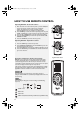
32602007GB.fm Page 32 Thursday, February 1, 2007 5:16 PM HOW TO USE REMOTE CONTROL Operating Guideline - General Procedures 1. After the main unit is connected to power, press the ON/OFF key on the remote control to start the air conditioner. (Note: The guide louver on main unit will be closed automatically when the air conditioner is switched off). 2. Press MODE key to select the desired operating mode, or press COOL or HEAT key to enter directly into corresponding mode. 3.
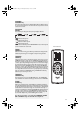
32602007GB.fm Page 33 Thursday, February 1, 2007 5:16 PM UP/DOWN UP/DOWN Key Press these two keys when in COOL, DRY, FAN or HEAT mode to set a temperature between 16 and 30°C. The temperature of each mode can be stored. FAN SPEED FAN Key Press this key to change the fan speed cyclically as follows: Indicates auto speed Indicates low speed. Indicates medium speed. Indicates high speed. Note: The fan is at low speed in DEHUMIDIFY mode.
32602007GB.fm Page 34 Thursday, February 1, 2007 5:16 PM JET JET key In COOL or HEAT mode, press this key to activate or disable the jet function. The JET icon will appear when the jet function is activated. The jet function will be automatically cancelled upon change of mode or fan speed. ROUND U ROUND key Press this key once to activate the ROUND U function, in which case the ROUND U icon will appear.
32602007GB.fm Page 35 Thursday, February 1, 2007 5:16 PM Replacement of Remote Control Battery and Precautions 1. Gently press down on the battery cover and push in the direction of the arrow to remove, as shown. 2. Remove the old batteries 3. Replace with two 7# dry cell batteries (AAA 1.5V). Ensure that “+” and “-” polarity is correctly positioned. 4. Close the battery cover on the remote control.
32602007GB.fm Page 36 Thursday, February 1, 2007 5:16 PM CLEANING AND MAINTENANCE Warning • Make sure to stop the unit and unplug it before cleaning your air conditioner. Otherwise you may risk electrocution. • Wetting of air conditioner may cause the risk of electrocution. Never wash your air conditioner. • Solvents such as paint thinner or gasoline will damage the appearance of the air conditioner. (Use only a soft dry or damp cloth and neutral detergent to clean the air conditioner cabinet).
32602007GB.fm Page 37 Thursday, February 1, 2007 5:16 PM Checks before Seasonal Use 1. Check the air inlet/outlet on indoor and outdoor units for any blocking. 2. Check the grounding cable for reliability. 3. Check the battery of the remote control for replacement. 4. Check the mounting frame of the outdoor unit for damage. If damaged, contact a Whirlpool Authorized Service Center. Maintenance after Seasonal Use 1. 2. 3. 4. Disconnect from the power supply. Clean the air filter.
32602007GB.fm Page 38 Thursday, February 1, 2007 5:16 PM TROUBLESHOOTING Warning: Do not attempt to repair the air conditioner yourself. Incorrect repairs may cause electrocution or fire, so please contact the Whirlpool Authorized Service Center nearest you for professional repairs. The following checks may save your time and costs.
32602007GB.fm Page 39 Thursday, February 1, 2007 5:16 PM Malfunction Indoor unit makes noise No air blows out of indoor unit Cause • The sound comes from the fan or compressor relay switching over (close/open). • Air conditioner may make noise in defrost mode or when stopped due to inverse flow of refrigerant in the unit • When the temperature of the indoor heat exchanger is low during heating process, the indoor unit will stop air blowing to prevent blowing of cold air (for 3 minutes).
32602007GB.fm Page 40 Thursday, February 1, 2007 5:16 PM INSTALLATION SERVICE PRECAUTIONS ON INSTALLATION Important Precaution 1. The air-conditioning unit must be installed according to national wiring rules and according to this manual by professionals. 2. Contact the local Whirlpool Service Center or qualified technician before installation 3. Any change of installation position must be handled by professionals. 4.
32602007GB.fm Page 41 Thursday, February 1, 2007 5:16 PM ELECTRICAL SAFETY REQUIREMENTS 1. The power supply must be of rated voltage with special circuitry for air-conditioning. The diameter of the power cord must comply with requirements. 2. Applicable voltage range: the normal operating range of voltage is 90%~110% of rated voltage. 3. Never pull the power cord. 4. Ensure safe grounding and a grounding wire connected with the special grounding system of the building, installed by professionals.
32602007GB.
32602007GB.fm Page 43 Thursday, February 1, 2007 5:16 PM INSTALLING INDOOR UNIT Installing Wall-Mount Frame 1. Level with plumb line or spirit level. As the drain outlet is on the left side, it is better for the left side to be lower when adjusting the wall-mounted board. 2. Use screws to secure the wall-mount frame on the wall. 3. After installation is completed, manually pull the wall-mount frame to check that it is secured.
32602007GB.fm Page 44 Thursday, February 1, 2007 5:16 PM Notes: If the connecting cable is not long enough, please contact the authorized service center for a length of special cable. No joints are allowed in the cable. • Make sure to connect the cable correctly. Incorrect connection will cause malfunction of some electrical parts. • Tighten the terminal screw to prevent slack. • After tightening the screw, gently pull the cable taut. • Incorrect connection of grounding cable may cause electrocution.
32602007GB.fm Page 45 Thursday, February 1, 2007 5:16 PM Cable connection 1. Remove the handle on the right side plate of the outdoor unit (one screw). 2. Remove the cable clamp, connect the power connection cable with the terminal on the connecting board and fasten it. The fitting line distribution must be consistent with the indoor unit. 3. Use cable clamp to fasten the cable connection. 4. Confirm the fitting lines are fixed. 5. Install the handle (fastened with one screw).
32602007GB.fm Page 46 Thursday, February 1, 2007 5:16 PM Vacuum-pumping and Leakage Inspection 1. Tighten the pipe nut entirely. 2. Take off the one-way valve cap of the cut off valve. 3. Loosen the valve stem of the liquid valve with a hex wrench. Valve core should be opened by screw driver, gas should be discharged. Air discharge lasts for 15seconds, then refrigerant flow out. Close the valve core and screw down the flare nut of the check valve. 4.
32602007GB.
32602007GB.fm Page 48 Thursday, February 1, 2007 5:16 PM ELECTRICAL CONNECTION 1) For Great Britain only Warning - this appliance must be earthed Fuse replacement If the mains lead of this appliance is fitted with a BS 1363A 13amp fused plug, to change a fuse in this type of plug use an A.S.T.A. approved fuse to BS 1362 type and proceed as follows: 1. Remove the fuse cover (A) and fuse (B). 2. Fit replacement 13A fuse into fuse cover. 3. Refit both into plug.