Gebrauchsanweisung Instructions for use Mode d’emploi Gebruiksaanwijzing Istruzioni per l’uso Instrukcje użytkowania Használati utasítás ИнструкциЯ за употреба Brugsanvisning Bruksanvisning Käyttöohje Manual de utilização Instrucciones para el uso Návod k použití Návod na použitie Instruc∑iuni de utilizare Инструкции по эксплуатации
AMD 335 - 336 ENGLISH 4 Instructions for use Page 4 3
BEFORE USING THE APPLIANCE To make the most out of your new appliance, please read the user instructions carefully and keep them handy for future consultation. SAFETY PRECAUTIONS • Never block the air inlet or outlet of indoor and outdoor unit. • Physically or mentally disabled people, children and people without any experience with the product are only allowed to use the appliance if they have had specific training on how to operate the appliance by a person responsible for their security and well-being.
SAFEGUARDING THE ENVIRONMENT • This appliance has been made of recyclable or re-usable material. Scrapping must be carried out in compliance with local waste disposal regulations. Before scrapping it, make sure to cut off the mains cord so that the appliance cannot be re-used. • For more detailed information on handling and recycling of this product, contact your local authorities who deal with the separate collection of rubbish or the shop where you bought the appliance.
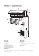
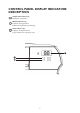
PRODUCT DESCRIPTION Outdoor unit 11. Air Intake 12. Pipes and Power Connection Cord 13. Drain Hose Note: Condensate water drains at COOLING or DRY operation. 14. Air Outlet Indoor unit 1. Air Intake 2. Front Panel 3. Display panel 4. Air Outlet 5. Electrical box 6. Emergency control button 7. Vertical Adjustment Louver 8. Horizontal Adjustment Louver 9. Air Filter 10.
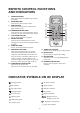
CONTROL PANEL DISPLAY INDICATORS DESCRIPTION Temperature indicator (1) Displays set temperature. Running indicator (2) It lights up during operation. It flashes during outside unit defrosting. Timer indicator (3) It lights up during the set time. It goes off when timer operation ends.
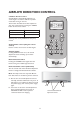
REMOTE CONTROL FUNCTIONS AND INDICATORS 1. ON/OFF BUTTON Starts and/or Stops the appliance by pressing this button. 2. MODE BUTTON Used to select the operation mode. 3. FAN BUTTON Used to select fan speed in sequence auto, high, medium or low. 4-5. TEMPERATURE BUTTON Used to select the room temperature. Used to set time in timer mode and real time clock. 6. 6TH SENSE BUTTON Sets or cancels 6th sense operation. 7.
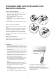
STORAGE AND TIPS FOR USING THE REMOTE CONTROL How to insert the batteries 1. Insert a pin and gently press down on the battery cover and push in the direction of the arrow to remove, as shown. 2. Insert 2 AAA batteries (1.5V) into the compartment. Ensure that "+" and "-" polarity is correctly positioned. 3. Close the battery cover on the remote control. How to remove the batteries Remove the battery cover in the direction of the arrow.
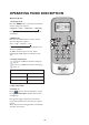
OPERATING MODE DESCRIPTION Operation Modes: 1. Selecting mode Each time MODE button is pressed, the operation mode is changed in sequence: COOLING → DRY → FAN ONLY → HEATING ↑ Heating mode is not available for cooling only air conditioners. 2. FAN mode Each time the "FAN" button is pressed, the fan speed is changed in sequence: Auto → High → Medium → Low ↑ At "FAN ONLY" mode, only "High","Medium" and "Low" are available.
AIRFLOW DIRECTION CONTROL 5. Airflow direction control Vertical airflow is automatically adjusted to a certain angle in accordance with the operation mode after turning on the unit. The direction of airflow can be also adjusted to your own requirement by pressing the "SWING" button of the remote control. Operation mode Direction of airflow COOLING, DRY horizontal *HEATING, FAN ONLY downward *Heating mode is only available for heat pump models.
MODE AND FUNCTION DESCRIPTIONS 6th SENSE MODE Press the button, the unit enters 6th sense mode directly regardless of the unit is on or off. In this mode, temperature and fan speed are automatically set based on the actual room temperature. Operation mode and temperature are determined by indoor temperature.
Clock function You can adjust the real time by pressing TIMER ON/CLOCK button, then using and buttons to get the correct time, press this button again, the real time is set. SLEEP mode SLEEP mode can be set in COOLING, HEATING or DRY operation mode. This function gives you a more comfortable environment for sleep. In SLEEP mode, • The appliance will stop operation automatically after operating for 8 hours. • Fan speed is automatically set at low speed.
Timer function It is convenient to set the timer on by pressing the TIMER ON/CLOCK button to achieve a comfortable room temperature at the time you get home. You can also set timer off by pressing the TIMER OFF button to enjoy a good sleep at night. How to set TIMER ON TIMER ON/CLOCK button can be used to set the timer programming as wished in order to switch on the appliance at your desired time.
Around U function When you press this button, will display, remote control transmits the actual room temperature around it to the indoor unit, and the appliance will operate according to this temperature to let you feel more comfortable. Please keep the remote control in a location where it can transmit the signal to the indoor unit properly. Press once to set and press again to cancel. DIM function Press this button to turn on or turn off display light on indoor unit control panel.
EMERGENCY OPERATION Under emergency situation or when remote control is missing, you can control the unit by pressing the on/off swith located on the indoor unit. • Turn on the appliance: when the unit is off, press this button, it will start up and operate in 6th SENSE mode. • Turn off the appliance: when the unit is on, press this button, the unit will stop working. on/off switch PROTECTION Operating condition The protective device maybe trip and stop the appliance in the cases listed below.
MAINTENANCE Clean front panel of Indoor Unit 1. Disconnect from the power supply Turn off the appliance first before disconnecting from power supply. 2. Remove the front panel Open the front panel as shown by the arrow (Fig. A). Pull the slots at the side of the front panel with force to take out the front panel (Fig. B). 3. Clean the front panel Wipe it with a soft and dry cloth. Use lukewarm water (below 40°C) to clean if the appliance is very dirty. After cleaning let it dry. 4.
TROUBLESHOOTING Operation problems are often due to minor causes, please check and refer to the following chart before contacting the service. This may save time and unnecessary expenses. Trouble Analysis Does not run • Is the protection device or fuse blown? • Please wait for 3 minutes and start again, protection device may be preventing unit to work.
INSTALLATION INSTRUCTIONS Installation diagram Distance from ceiling should be over 200mm Distance from wall should be over 50mm Distance from the wall should be over 50mm Indoor unit Distance from floor should be over 2500mm Outdoor unit Air intake distance from the wall should be over 250mm Air intake distance from the wall should be over 250mm Ai shor out uld let be dist ov anc er e f 50 rom 0m m the wa ll Over 250mm NOTE: The figure above is only a simple presentation of the unit, it may not m
Select the best location Location for Installing Indoor Unit • Where there is no obstacle near the air outlet and air can be easily blown to every corner of room. • Where piping and wall hole can be easily arranged. • Observe the required distance from ceiling and wall according to the installation diagram. • Where the air filter can easily be removed. • Keep the unit and remote control 1m or more from television, radio etc.
INSTALLATION SERVICE Before installation 1. Please read this manual carefully before installation. 2. The appliance must be installed according to national wiring rules and according to this manual by qualified technicians. 3. Any change of installation position must be handled by professionals; 4. Check the product to verify that it has not been damaged before installation. 5. Mount with the lowest moving parts of indoor unit at least 2.5m above floor or grade Level. 6.
INDOOR UNIT INSTALLATION 1. Installing the Mounting Plate • Select a location to install the mounting plate according to the indoor unit location and piping direction. • Adjust the mounting plate horizontally with a gradienter or plumb line. • Drill holes 32mm in deep on the wall to fix the plate. • Insert the plastic plugs in the hole, then fix the mounting plate with tapping screws. • Check that the mounting plate is well fixed. Then drill a hole for piping.
IMPORTANT: Piping Joints Thermal Insulation: Wrap the piping joints with thermal insulating materials and then wrap with a vinyl tape. Wrapped with vinyl type Thermal insulation Thermal Insulation piping: a. Place the drain hose under the piping. b. Insulation material: polythene foam over 6mm in thickness. NOTE: Drain hose is prepared by user. Large pipe • Drain hose should point downward for easy drain flow.
4. Connecting the Cable • Indoor Unit 1) Open the front panel, remove the covering plate by loosening the screw. 2) Connect the power connecting cord to the indoor unit by connecting the wires to the terminals on the control board individually as follows. 3) Secure the power connecting cord on the control board with cable clamp. 4) Refit the covering plate and tighten the screw.
WIRING DIAGRAM 18K/24K Models Outdoor unit Indoor unit Terminal Terminal 1L N Brown Brown 1L Blue Blue N Power connecting cord Yellow/Green Yellow/Green Electric Box Note: For 18k, 24k models, the power supply are connected from indoor unit with a circuit breaker. For some models, the ground wire may be connected to the electric box directly. OUTDOOR UNIT INSTALLATION 1. Install Drain Port and Drain Hose The condensate drains from the outdoor unit when the unit operates in heating mode.
AIR PURGING Air containing moisture remaining in the refrigeration cycle may cause a malfunction on the compressor. After connecting the indoor and outdoor units, evacuate air and moisture from refrigerant cycle using a vacuum pump, as shown below. Note: Because the system pressure is high and also to protect the environment, be sure not to discharge the refrigerant to the air directly.
AFTER SALES SERVICE If repair work has to be carried out, contact the Customer Care Centre (Use of original spare parts and a proper repair is guarenteed). You will need to present the original invoice. Failure to comply with these instructions could compromise the safety and quality of your product. Before contacting the Customer Care Centre: 1. Try to solve the problem yourself based on the descriptions given in the "Troubleshooting". 2. Turn the appliance off and restart it to see if the fault persists.
5019 326 02066 GB AE Whirlpool® Registered trademark/TM Trademark of Whirlpool group of companies - © Copyright Whirlpool Europe s.r.l. 2012. All rights reserved - http://www.whirlpool.