INSTALLATION INSTRUCTIONS COMMERCIAL DRYER – Gas or Electric INSTRUCTIONS POUR L’INSTALLATION D’UNE SÉCHEUSE COMMERCIALE – À gaz ou électrique Para una versión de estas instrucciones en español, visite www.whirlpool.com TABLE OF CONTENTS TABLE DES MATIÈRES DRYER SAFETY ............................................................................ 2 INSTALLATION REQUIREMENTS .............................................. 4 Tools and Parts .....................................................................
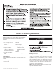
DRYER SAFETY ■ ■ 2 It is recommended that the owner post, in a prominent location, instructions for the customer’s use in the event the customer smells gas. This information should be obtained from your gas supplier. Post the following warning in a prominent location.
WARNING: Gas leaks cannot always be detected by smell. Gas suppliers recommend that you use a gas detector approved by UL or CSA. For more information, contact your gas supplier. If a gas leak is detected, follow the “What to do if you smell gas” instructions.
INSTALLATION REQUIREMENTS Tools and Parts Location Requirements Gather the required tools and parts before starting installation. Read and follow the instructions provided with any tools listed here.
Recessed Area and Closet Installation Instructions Product Dimensions 27" (68.6 cm) dryer This dryer may be installed in a recessed area or closet. For recessed area and closet installations, minimum clearances can be found on the warning label on the rear of the dryer. The installation spacing is in inches and is the minimum allowable. Additional spacing should be considered for ease of installation, servicing, and compliance with local codes and ordinances.
Electrical Requirements – Gas Dryer Recommended Ground Method The dryer, when installed, must be electrically grounded in accordance with local codes or, in the absence of local codes, with the National Electrical Code, ANSI/NFPA 70, latest edition, or Canadian Electrical Code, CSA C22.1, and all local codes and ordinances. GROUNDING INSTRUCTIONS ■ For a grounded, cord-connected dryer: This dryer must be grounded.
Electrical Requirements – U.S.A. Only It is your responsibility ■ To contact a qualified electrical installer. ■ To be sure that the electrical connection is adequate and in conformance with the National Electrical Code, ANSI/NFPA 70-latest edition and all local codes and ordinances. The National Electrical Code requires a 4-wire power supply connection for homes built after 1996 and dryer circuits involved in remodeling after 1996.
If connecting by direct wire: Power supply cable must match power supply (4-wire or 3-wire) and be: ■ Flexible armored cable or nonmetallic sheathed copper cable (with ground wire), protected with flexible metallic conduit. All current-carrying wires must be insulated. ■ 10-gauge solid copper wire (do not use aluminum). ■ At least 5 ft (1.52 m) long. ■ To supply the required 4 wire, single phase, 120/240 volt, 60 Hz., AC only electrical supply on a separate 30-amp circuit, fused on both sides of the line.
Gas Supply Requirements Gas Supply Line Recommended method ■ Provide a gas supply line of 1/2" (13 mm) rigid (IPS) pipe to the dryer location. Pipe joint compounds that resist the action of LP gas must be used. Do not use TEFLON®† tape with LP gas. Minimum tubing diameter for LP gas is 1/2" (13 mm). Usually, LP gas suppliers determine the size and materials used in the system. Alternate method ■ The gas supply may also be connected using 3/8" (10 mm) approved copper or aluminum tubing.
■ Installed in a confined area: If the dryer is installed in a confined area such as a bathroom or closet, provision must be made for enough air for combustion and ventilation. Check governing codes and ordinances or refer to the “Recessed Area and Closet Installation Instructions” in the Location Requirements section. Exhaust hood must be at least 12" (305 mm) from the ground or any object that may be in the path of the exhaust (such as flowers, rocks, or bushes).
Multiple Dryer Venting ■ A main vent can be used for venting a group of dryers. The main vent should be sized to remove 200 CFM of air per dryer. Large-capacity lint screens of proper design may be used in the main vent if checked and cleaned frequently. The room where the dryers are located should have make-up air equal to or greater than the CFM of all the dryers in the room.
INSTALLATION INSTRUCTIONS – GAS DRYER Make Gas Connection Complete Installation 1. With dryer in final position, place level on top of the dryer, first side to side; then front to back. If the dryer is not level, adjust the legs of the dryer up or down until the dryer is level. 1. Remove red cap from gas pipe on back of dryer. 2. Connect gas supply to dryer. Use a pipe thread compound approved for the type of gas supplied. If flexible metal tubing is used, be certain there are no kinks.
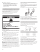
INSTALLATION INSTRUCTIONS – ELECTRIC DRYER Power Supply Cord 1. Disconnect power. 2. Remove the hold-down screw and terminal block cover. D C B A A. Neutral ground wire B. External ground conductor screw C. Center terminal block screw D. Terminal block cover and holddown screw 3. Install strain relief.
Power supply cord strain relief: ■ Remove the screws from a 3/4" (19 mm) UL listed strain relief (UL marking on strain relief). Put the tabs of the two clamp sections into the hole below the terminal block opening so that one tab is pointing up and the other is pointing down, and hold in place. ■ Put power supply cord through the strain relief. Be sure that the wire insulation on the power supply cord is inside the strain relief.
3. Connect ground wire (green or bare) of power supply cord to external ground conductor screw. Tighten screw. Power supply cord, 4-wire connection: IMPORTANT: A 4-wire connection is required where local codes do not permit the use of 3-wire connections. A F B D E B A F C C D G E A. 4-wire receptacle (NEMA type 14-30R) B. 4-prong plug C. Ground prong D. Neutral prong E. Spade terminals with upturned ends F. 3/4" (19 mm) UL listed strain relief G. Ring terminals A.
Power supply cord, 3-wire connection: B D E A C G F Use where local codes permit connecting cabinet-ground conductor to neutral wire. 1. Loosen or remove center terminal block screw. 2. Connect neutral wire (white or center wire) of power supply cord to the center terminal screw of the terminal block. Tighten screw. 3. Connect the other wires to outer terminal block screws. Tighten screws. A. 3-wire receptacle (NEMA type 10-30R) B. 3-wire plug C. Neutral prong D. Spade terminals with upturned ends E.
Direct wire cable must match power supply (4-wire or 3-wire) and be: ■ Flexible armored cable or nonmetallic sheathed copper cable (with ground wire), covered with flexible metallic conduit. All current-carrying wires must be insulated. ■ 10-gauge solid copper wire (do not use aluminum). ■ At least 5 ft. (1.52 m) long. 1. Disconnect power. 2. Remove hold-down screw and terminal block cover. Direct Wire Method – U.S. Only D C A. Neutral ground wire B. External ground conductor screw C.
Direct Wire, 4-wire connection: D A IMPORTANT: A 4-wire connection is required where local codes do not permit the use of 3-wire connections. Direct wire cable must have 5 ft (1.52 m) of extra length so dryer can be moved if needed. Strip 5" (127 mm) of outer covering from end of cable, leaving bare ground wire at 5" 1" ) (127 mm). Cut 11⁄2" (38 mm) mm (25 from 3 remaining wires. Strip insulation back 1" (25 mm). Shape ends of wires into a hook shape.
Direct wire, 3-wire connection: C A Use where local codes permit connecting cabinet-ground conductor to neutral wire. Direct wire cable must have 5 ft (1.52 m) of extra length so dryer can be moved if needed. 1" m) Strip 31⁄2" (89 mm) of outer (25 m covering from end of cable. Strip insulation back 1" (25 mm). If using 3-wire cable with ground wire, cut bare wire even with outer 31 ⁄2" covering. Shape ends of wires into (89 mm) a hook shape.
Connect Vent 1. Using a 4" (102 mm) clamp, connect vent to exhaust outlet in dryer. If connecting to existing vent, make sure the vent is clean. The dryer vent must fit over the dryer exhaust outlet and inside the exhaust hood. Make sure the vent is secured to exhaust hood with a 4" (102 mm) clamp. 2. Move dryer into final position. Do not crush or kink vent, and remove any excess flexible vent to improve airflow. Make sure dryer is level. Complete Installation 1.
REVERSING THE DOOR SWING Door swing can be changed from a right-side opening to left-side opening, if desired. Place a towel or soft cloth on top of the dryer or work space to avoid scratching the surface. Remove the Door Assembly Reverse Hinge 1. Use a small flat-blade screwdriver to remove 2 plug strips from the inner door. Slide the head of the screwdriver under the plugs, being certain not to scratch the inner door surface. Lift up. 1.
Reverse the strike 1. Use a small flat-blade screwdriver to remove plug strip from the dryer door opening. Slide the head of the screwdriver under the plugs, being certain not to scratch the dryer surface. Lift the plastic strip from the dryer slowly to avoid distortion of the plug strip. 2. Remove the strike using a Phillips screwdriver. 3. Insert strike on the opposite side. Reinstall the door 1. Reattach door to dryer front panel with the 4 screws.
ELECTRONIC CONTROL SETUP GENERAL USER INFORMATION Scrolling “out of order” message, followed by a failure or diagnostic code, showing in display This condition indicates the dryer is inoperative. ‘0 Minutes’ showing in display This condition indicates the dryer cannot be operated. Coins dropped or debit inputs during this condition will be stored in escrow but cannot be used until normal operation is restored by opening and closing the door.
IMPORTANT: To access set-up mode or diagnostic mode, use a service key to open the service access door. If a card reader is installed, a service card is available for accessing diagnostics. If a service key is not available, the AA1 connector must be removed for access. The console must not be opened unless power is first disconnected from the dryer. To access connector AA1: 1. Unplug dryer or disconnect power. 2. Open console, remove plug on AA1, close console. 3. Plug in dryer or reconnect power.
CODE EXPLANATION CODE OPTIONS TO USE IF SPECIAL PRICING IS SELECTED (continued): SPECIAL PRICE DAY O VAULT VIEWING OPTION Both coin & debit selected. Press the COLORS/DELICATES button 3 consecutive times to change this selection. J This represents the day of the week and whether special pricing C is selected for that day. A number followed by ‘0’ indicates no selection that particular day (9.10). A number followed by an ‘S’ indicates selected for that day (9.1S).
CDRYER DIAGNOSTIC MODE DIAGNOSTIC CODES If the set-up mode is entered and one of the following has previously occurred, the appropriate diagnostic code will be in the display. DRYER DISPLAY/ DRYER AFFICHAGE DISPLAY/ DE LA SÉCHEUSE EXPLANATION Blocked coin 1 or coin drop UI control circuit failure (coin recognition and customer display disabled while blockage persists). Voltage detected below 90 VAC for 8 seconds.
WHIRLPOOL® COMMERCIAL LAUNDRY WARRANTY: CAM2752, CEM2750, CGM2751, CAM2762, CEM2760, CGM2761, CSP2760, CSP2761, CEW9100, CGW9100, CHW9900, CED8990, CGD8990, YCEW9100, YCED8990 LIMITED WARRANTY For the first three years from the date of purchase, when this commercial appliance is installed, maintained, and operated according to the instructions attached to or furnished with this product, Whirlpool Corporation (thereafter “Whirlpool”) will pay for factory specified parts or original equipment manufacturer par
SÉCURITÉ DE LA SÉCHEUSE ■ ■ 28 On recommande que le propriétaire place les instructions à l’usage du client à un endroit bien visible, pour le cas où le client percevrait une odeur de gaz. Ces renseignements doivent être obtenus auprès de votre fournisseur de gaz. Placer l’avertissement qui suit à un endroit bien visible.
EXIGENCES D’INSTALLATION Outillage et pièces Rassembler les outils et pièces nécessaires avant de commencer l'installation. Lire et respecter les instructions d’installation fournies avec chacun des outils de cette liste.
Distances de séparation minimales Dimensions du produit – Sécheuse de 27" (69 cm) 14" (356 mm) max. 15" (381 mm)* 27" (686 mm) Porte du placard 5" (52 mm) 0" (0 mm) CÂBLE ÉLECTRIQUE VUE ARRIÈRE 0" (0 mm) 1" (25 mm) Encastrement, vue avant Placard, vue latérale * On doit prévoir un espacement additionnel pour tenir compte éventuellement des moulures du mur, de la porte et du plancher, ou si le circuit d’évacuation comporte un coude. 61⁄4" (159 mm) 13" (330 mm) 283⁄4" (733 mm) 4" (102 mm) dia.
Spécifications électriques - sécheuse à gaz Méthode recommandée de liaison à la terre Après l’installation, la sécheuse doit être électriquement reliée à la terre conformément aux prescriptions des codes et règlements locaux; en l’absence de code local, respecter les prescriptions du code national en vigueur : National Electrical Code, ANSI/NFPA 70 (édition la plus récente), ou Code canadien de l’électricité, CSA C22.1, ainsi que celles des codes et règlements locaux.
Spécifications électriques Pour le Canada seulement INSTRUCTIONS DE LIAISON À LA TERRE Pour une sécheuse reliée à la terre et connectée par un cordon : Cette sécheuse doit être reliée à la terre. En cas de mauvais fonctionnement ou de panne, la liaison à la terre réduira le risque de choc électrique en offrant au courant électrique un acheminement d'évacuation de moindre résistance.
Spécifications de l’alimentation en gaz AVERTISSEMENT Risque d’explosion Utiliser une canalisation neuve d’arrivée de gaz approuvée par la CSA International. Installer un robinet d’arrêt. Bien serrer chaque organe de connexion de la canalisation de gaz. En cas de connexion au gaz propane, demander à une personne qualifiée de s’assurer que la pression de gaz ne dépasse pas 330 mm (13 po) de la colonne d’eau.
■ Robinet d’arrêt nécessaire : Conformément aux prescriptions du National Fuel Gas Code, ANSI Z223.1, on doit installer un robinet d’arrêt manuel sur la canalisation d’alimentation, à moins de 6 pi (1,8 m) de la sécheuse. Au Canada, le robinet d’arrêt manuel doit être installé conformément aux prescriptions des codes d’installation B149 – CAN/CGA B149.1 et CAN/CGA B149.2. Le robinet d’arrêt doit être situé dans la même pièce que la sécheuse.
Longueur du circuit d'évacuation La longueur maximale du circuit d’évacuation dépend du type de conduit utilisé, du nombre de coudes et du type de bouche de décharge. La longueur maximale pour le circuit de conduit rigide ou flexible est indiquée dans le tableau ci-après. Longueur maximale du conduit Chaque conduit d’évacuation devrait pénétrer dans le conduit principal à un angle pointant dans la direction du débit d’air.
INSTRUCTIONS D’INSTALLATION – GLISSIÈRE ET CAISSE À MONNAIE Installation d’une glissière et d’une caisse à monnaie Le mécanisme de paiement, la serrure et la clé du tableau de commande et la serrure et la clé de réceptacle des pièces ne sont pas inclus; on peut les obtenir auprès des sources usuelles de l’industrie. Pour ce modèle, on doit utiliser un dispositif spécial d’extension de glissière que l’on peut acheter auprès d’un distributeur de glissières.
Achever l’installation 1. Une fois la sécheuse à son emplacement final, placer un niveau sur le sommet de la sécheuse, transversalement, puis dans le sens avant arrière. Si la sécheuse n’est pas d’aplomb, ajuster les pieds pour modifier la hauteur et établir un bon aplomb de la sécheuse. 2. Brancher sur une prise à 3 alvéoles reliée à la terre. 38 3. Contrôler le bon fonctionnement de la sécheuse: Fermer la porte de la sécheuse.
INSTRUCTIONS D’INSTALLATION – SÉCHEUSE ÉLECTRIQUE Raccordement du conduit d’évacuation 1. À l’aide d’une bride de fixation de 4" (102 mm), relier le conduit d’évacuation à la bouche d’évacuation de la sécheuse. Si on utilise le conduit d’évacuation existant, s’assurer qu’il est propre. Le conduit d’évacuation de la sécheuse doit être fixé sur la bouche d’évacuation de la sécheuse et dans le clapet d’évacuation.
INVERSION DU SENS D’OUVERTURE DE LA PORTE Le sens d’ouverture de la porte peut être changé du côté droit au côté gauche, si désiré. Placer une serviette ou un linge doux sur le dessus de la sécheuse ou du plan de travail pour empêcher rayer la surface. 4. Soulever la partie interne de la porte hors de la partie externe. 5. Faire pivoter la partie externe de 180°. Ôter la porte 1. Enlever 3 des 4 vis qui maintiennent la charnière de la porte sur le panneau avant de la sécheuse.
2. Ôter les 4 vis qui fixent la charnière de la porte interne et déplacer la charnière de l’autre côté. Réinstaller les 4 vis. Inversion de la gâche 1. Utiliser un petit tournevis à lame plate pour enlever la tringle des pitons d’obturation des trous dans l’ouverture de la porte de la sécheuse. Faire glisser la tête du tournevis sous les tringles, en veillant à ne pas érafler la surface de la sécheuse.
INSTRUCTIONS D’ENTRETIEN Instructions d’entretien : Nettoyer le filtre à charpie après chaque utilisation. ■ Comment enlever la charpie accumulée : • De l’intérieur de la sécheuse : Il faut retirer la charpie tous les 2 ans ou plus souvent, selon l’utilisation de la sécheuse. Le nettoyage doit être effectué par une personne qualifiée. • Du conduit d’évacuation : Il faut retirer la charpie tous les 2 ans ou plus souvent, selon l’utilisation de la sécheuse.
RÉGLAGE DE COMMANDE ÉLECTRONIQUE INFORMATION GÉNÉRALE POUR L’UTILISATEUR Défilement de “out of order” (hors service) sur l’afficheur, suivi par un code de défaillance ou un code de diagnostic Cette situation indique que la sécheuse n’est pas opérationnelle. Affichage de ‘0 Minutes’ Ceci indique qu’il n’est pas possible de faire fonctionner la sécheuse.
DISPLAY AFFICHEUR AFFICHEUR Après l’installation initiale et le branchement de la sécheuse, l’afficheur présente Aprèsthe l’installation initialeinstalled et le branchement sécheuse, l’afficheur After dryer has been and pluggedde in,lathe display will show présente Après l’ouverture et la fermeture de la porte, l’afficheur présente le prix ‘0 minutes.’ MINUTES’.After Après et la fermeture la porte, le MINUTES’.
CODE EXPLICATION EXPLANATION E OPTION COMPTEUR DE MONNAIE Cette option peut être Sélectionnée (‘ON’) ou Pas sélectionnée (‘OFF’). Pas sélectionnée (‘OFF’). Option sélectionnée (‘ON’). Appuyer 3 fois consécutives sur la touche COLORS/DELICATES pour sélectionner ‘ON’ (active); appuyer 3 fois sur la touche pour désélectionner l’option (Pas sélectionnée [‘OFF’]). Le compteur passe de ‘OFF’ (inactive) à ‘ON’ (active). Option sélectionnée et impossibilité de désélection.
CODE EXPLANATION EXPLICATION OPTIONS TO USE IFOPTIONS SPECIALÀPRICING SELECTED (continued): UTILISERISAPRÈS SÉLECTION DE PRIX SPÉCIAL (suite)O : JOUR POUR PRIX SPÉCIAL Ceci représente le jour de la semaine sélectionné, et la sélection de la tarification spéciale pour ce jour. Un chiffre suivi de ‘0’ indique que cette option n’est pas sélectionnée pour le jour particulier concerné (9.10). Un chiffre suivi d’un ‘S’ indique que cette option est sélectionnée pour le jour concerné (9.1S).
EXPLICATION EXPLANATION CODE E OPTION PIÈCES/DÉBIT Sélection du paiement par pièces et par carte de débit. Appuyer 3 fois consécutives sur la touche COLORS/DELICATES pour changer cette sélection. Paiement par carte de débit sélectionné, paiement par pièces désactivé. Cette sélection doit être utilisée pour une utilisation gratuite. Appuyer 3 fois consécutives sur la touche COLORS/ DELICATES pour changer cette sélection. Paiement par pièces sélectionné; paiement par carte de débit désactivé.
CODES DE DIAGNOSTIC CODES DE DIAGNOSTIC Si un des événements est survenu avant Si un des événements suivants est survenu avantsuivants qu’on accède au mode dequ’on accède au mode de paramétrage, le codesera de diagnostic paramétrage, le code de diagnostic approprié visible sur approprié l’afficheur.sera visible sur l’afficheur.
SÉCHEUSE – MODE DE DIAGNOSTIC Pour accéder à ce mode, appuyer pendant une seconde sur la touche COLORS/ DELICATES alors que l’afficheur présente les codes de paramétrage 6 xx ou 7 xx ou lorsqu’un code de diagnostic est affiché. Les codes de diagnostic sont alors effacés et tous les segments de l’afficheur devraient clignoter. Si l’affichage d’un code de diagnostic persiste, on doit effectuer les opérations correctives nécessaires avant d’accéder le programme de diagnostic.
NOTES 50
W10184516C W10184517C–SP © 2011 All rights reserved. Tous droits réservés. ® Registered Trademark/TM Trademark of Whirlpool, U.S.A., Whirlpool Canada LP Licensee in Canada ® Marque déposée/TM Marque de commerce de Whirlpool, U.S.A., emploi sous licence par Whirlpool Canada LP au Canada 03/2011 Printed in U.S.A. Imprimé aux É.-U.