INSTALLATION INSTRUCTIONS COMMERCIAL DRYER – Gas or Electric INSTRUCTIONS POUR L’INSTALLATION D’UNE SÉCHEUSE COMMERCIALE – À gaz ou électrique Table of Contents/Table des matières . . . . . . . . . . . . . . . . . . . . . . . . . . . . . . . . . . . . . . . . 2 8577208 www.whirlpool.
TABLE OF CONTENTS TABLE DES MATIÈRES DRYER SAFETY............................................................................ 2 INSTALLATION REQUIREMENTS .............................................. 4 Tools and Parts .......................................................................... 4 Location Requirements.............................................................. 4 Electrical Requirements ............................................................ 6 Gas Supply Requirements .................
WARNING: For your safety, the information in this manual must be followed to minimize the risk of fire or explosion, or to prevent property damage, personal injury, or death. – Do not store or use gasoline or other flammable vapors and liquids in the vicinity of this or any other appliance. – WHAT TO DO IF YOU SMELL GAS: • Do not try to light any appliance. • Do not touch any electrical switch; do not use any phone in your building. • Clear the room, building, or area of all occupants.
INSTALLATION REQUIREMENTS Tools and Parts Gather the required tools and parts before starting installation. Read and follow the instructions provided with any tools listed here. Location Requirements WARNING Tools needed ■ ■ ■ ■ ■ ■ ■ ■ ■ ■ ■ ■ ■ 8" or 10" Pipe wrench 8' or 10" adjustable wrench Flat-blade screwdriver Phillips screwdriver Adjustable wrench that opens to 1" (2.
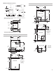
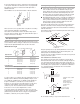
Minimum Installation Clearances Product Dimensions 27" (68.6 cm) dryer 14" (35.6 cm) max. 15" (38.1 cm)* 27" (68.6 cm) Closet door ELECTRIC 14" (35.6 cm) 0" (0 cm) 0" (0 cm) BACK VIEW 0" (0 cm) 1" (2.5 cm) Recessed front view Closet side view 6 ³⁄₄" (15.2 cm) Additional clearances for wall, door and floor moldings may be required or if external exhaust elbow is used. 13" (33 cm) 4" (10.2 cm) dia. 37" (94 cm) 4 ³⁄₄" (12.1 cm) GAS EXHAUST 3" (7.6 cm) 48 in2. (310 cm2)* 1¹⁄₄" (3.
Electrical Requirements – Gas Dryer WARNING Recommended Ground Method The dryer, when installed, must be electrically grounded in accordance with local codes or, in the absence of local codes, with the National Electrical Code, ANSI/NFPA 70, latest edition, or Canadian Electrical Code, CSA C22.1, and all local codes and ordinances. GROUNDING INSTRUCTIONS Electrical Shock Hazard Plug into a grounded 3 prong outlet. Do not remove ground prong. Do not use an adapter. Do not use an extension cord.
Recommended Ground Method ■ In U.S.: It is your responsibility to contact a qualified electrical installer to ensure that the electrical installation is adequate and in conformance with the National Electrical Code, ANSI/NFPA 70, latest edition, and all local codes and ordinances. ■ In Canada: It is your responsibility to install the dryer in accordance with Canadian Electrical Code, CSA C22.1 installation codes and all national or local codes.
Gas Supply Line Recommended method ■ Provide a gas supply line of ¹⁄₂" rigid (IPS) pipe to the dryer location. Pipe joint compounds that resist the action of LP gas must be used. Do not use TEFLON®† tape. With LP gas, piping or tubing size can be ¹⁄₂" minimum. Usually, LP gas suppliers determine the size and materials used in the system. Alternate method ■ The gas supply may also be connected using ³⁄₈" approved copper or aluminum tubing. If the total length of the supply line is more than 20 feet (6.
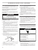
If using an existing vent system, clean lint from the entire length of the system and make sure exhaust hood is not plugged with lint. Replace any plastic or metal foil vent with rigid metal or flexible metal vent. Plan installation to use the fewest number of elbows and turns. A B Exhaust Air Flow A. Better B. Good Allow as much room as possible when using elbows or making turns. Bend vent gradually to avoid kinking. Vent outlet is located at the center of the bottom dryer back.
INSTALLATION INSTRUCTIONS – GAS DRYER Install Coin Slide and Coin Box The console houses the factory-installed accumulator timer with actuating arm and button. The factory-installed timer is set to provide 45 minutes (4 pins) of drying time when activated by the coin slide. Timer cams for 30-minute (6 pins) and 60-minute (3 pins) drying times are included in the parts bag.
(not the air cycle), let the dryer run for at least five minutes. Dryer will stop when time is used up. NOTE: Dryer door must be closed for dryer to operate. When door is open, dryer stops, but timer continues to run. To restart dryer, close door and push START/RESTART button. 4. If the burner does not ignite and you can feel no heat inside the dryer, shut off dryer for five minutes. Check that all supply valve controls are in “ON” position and that the electrical cord is plugged in.
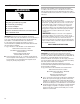
2. Remove hold-down screw and the terminal block cover. A 3. Assemble ³⁄₄" UL-listed strain relief (UL marking on strain relief) into the hole below the terminal block opening. Tighten strain relief screws just enough to hold the two clamp sections together. Install power supply cord through the D C B B A A. External ground conductor screw B. Tab C. Terminal block cover D. Hold-down screw C A. Strain relief clamp sections B. Dryer cabinet C. Strain relief screws strain relief. 4.
Power Supply Cord, Three-wire electrical connection: 5. Loosen or remove the center terminal block screw. 6. Connect the neutral wire (white or center) of the power supply cord to the center, silver-colored terminal screw of the terminal block. Tighten screw. 7. Connect the other wires to outer terminal block screws. Tighten screws. 8. Tighten strain relief screws. 9. Insert tab of the terminal block cover into slot of the dryer rear panel. Secure cover with hold-down screw.
1. Disconnect power. 2. Remove hold-down screw and terminal block cover. Direct Wire Method – U.S. Only A WARNING D C B A. External ground conductor screw B. Tab C. Terminal block cover D. Hold-down screw Fire Hazard Use 10 gauge solid copper wire. Use a UL listed strain relief. Disconnect power before making electrical connections. Connect neutral wire (white or center wire) to center terminal (silver). Ground wire (green or bare wire) must be connected to green ground connector. 3.
Direct Wire, Three-wire electrical connection: Three wire with ground wire: green or bare wire cut short. Wire is not used. Dryer is grounded through neutral conductor. A to disconnect box 1" (2.5 cm) of wires stripped of insulation B C 3-1/2" (8.9 cm) Shape ends of wires into a hook. Strip 3¹⁄₂" (8.9 cm) of outer covering from end of cable. Strip insulation back 1" (2.5 cm). If using 3 wire cable with ground wire, cut green or bare wire even with outer covering. A. ³⁄₄" conduit connector B.
CHANGING TO A 30- OR 60-MINUTE TIMING CAM WARNING Electrical Shock Hazard Disconnect power before making cam changes. Failure to follow these instructions can result in death or electrical shock. You can install the 30-minute or 60-minute timing cam (shipped with dryer) as follows: 1. Unplug dryer or disconnect power. 2. Unlock meter case. 3. Turn the timing cam by hand until the V-shaped notch lines up below the ratchet tooth. A B C D A. Ratchet tooth B. Timing cam C. Drive lug D. V-shaped notch 4.
Maintenance instructions: ■ Clean lint screen after each cycle. ■ Removing accumulated lint: ■ From inside the dryer cabinet: Lint should be removed every 2 years or more often, depending on dryer usage. Cleaning should be done by a qualified person. ■ From the exhaust vent: Lint should be removed every 2 years, or more often, depending on dryer usage.
NOTES 18
SÉCURITÉ DE LA SÉCHEUSE Votre sécurité et celle des autres est très importante. Nous donnons de nombreux messages de sécurité importants dans ce manuel et sur votre appareil ménager. Assurez-vous de toujours lire tous les messages de sécurité et de vous y conformer. Voici le symbole d’alerte de sécurité. Ce symbole d’alerte de sécurité vous signale les dangers potentiels de décès et de blessures graves à vous et à d’autres.
IMPORTANTES INSTRUCTIONS DE SÉCURITÉ AVERTISSEMENT : Pour réduire le risque d'incendie, de choc électrique ou de blessure lors de l'utilisation de la sécheuse, il convient d'observer certaines précautions élémentaires dont les suivantes : I I I I I I I I Lire toutes les instructions avant d'utiliser la sécheuse. Ne pas placer des articles exposés aux huiles de cuisson dans votre sécheuse.
EXIGENCES D’INSTALLATION Outillage et pièces Rassembler les outils et pièces nécessaires avant de commencer l'installation. Lire et respecter les instructions d’installation fournies avec chacun des outils de cette liste.
Dimensions du produit – Sécheuse de 27" (68,6 cm) 3" (7,6 cm) 48 po2 (310 cm 2 )* 27" (68,6 cm) vue avant Porte du placard CÂBLE ÉLECTRIQUE 24 po2 (155 cm 2 )* 14" (35,6 cm) 37" (94 cm) VUE ARRIÈRE 3" (7,6 cm) 6 ³⁄₄" (15,2 cm) 13" (33 cm) dia. 4" (10,2 cm) * Taille minimale de l’ouverture pour la porte du placard. On peut utiliser une porte à jalousies offrant une surface de passage d’air équivalente.
Spécifications électriques - sécheuse à gaz AVERTISSEMENT Méthode recommandée de liaison à la terre Après l’installation, la sécheuse doit être électriquement reliée à la terre conformément aux prescriptions des codes et règlements locaux; en l’absence de code local, respecter les prescriptions du code national en vigueur : National Electrical Code, ANSI/NFPA 70 (édition la plus récente), ou Code canadien de l’électricité, CSA C22.1, ainsi que celles des codes et règlements locaux.
■ Aux É.-U. : L’appareil doit être alimenté par un circuit indépendant monophasé à quatre conducteurs ou trois conducteurs, 120/240 V, 60 Hz, CA seulement (ou un circuit 120/208 V à trois ou quatre conducteurs si ceci est spécifié sur la plaque signalétique); chaque conducteur de phase du circuit doit être protégé par un fusible 30 A; on recommande l’emploi de disjoncteurs ou fusibles temporisés.
Type de gaz La sécheuse est équipée pour l’alimentation au gaz naturel. Elle est homologuée par CSA International pour l’alimentation avec des gaz de pétrole liquefies (propane et butane), après conversion appropriée. Ne pas entreprendre de convertir l’appareil pour l’utilisation d’un gaz différent de celui indiqué sur la plaque signalétique sans d’abord consulter le fournisseur de gaz. Un technicien qualifié doit effectuer la conversion.
■ Utiliser un conduit d’évacuation en métal lourd de 4" (10,2 cm) et des brides de fixation. ■ Utiliser des brides de fixation pour sceller tous les joints. L'évent ne doit pas être connecté ou fixé avec des vis ou autres dispositifs d'accrochage qui se prolongent à l'intérieur de l'évent. Ne pas utiliser de ruban adhésif en toile. IMPORTANT : Respecter les dispositions de tous les codes et règlements en vigueur. Utiliser un conduit d'évacuation en métal lourd.
L’angle maximal entre le conduit connecté à une sécheuse et le conduit principal ne devrait pas dépasser 30°. A 30° max. débit d’air B Si une bouche de décharge ne peut être utilisée : L’extrémité extérieure du conduit principal devrait être munie d’un coude de déviation dirigé vers le bas.
Pour une sécheuse dotée d’un mécanisme d’insertion à glissière, utiliser l’ensemble d’adaptation fourni avec la sécheuse. 7. Réinstaller la plaque de l’ouverture d’accès du boîtier de commande. Placer la boîte à pièces avec la serrure et la clé dans l'ouverture d'accès du boîtier de commande. 8. Retirer la feuille de carton ou le panneau de bois dur placé sous la sécheuse. Raccordement à la canalisation de gaz 1. Retirer le capuchon rouge de la canalisation de gaz. 2.
INSTRUCTIONS D’INSTALLATION – SÉCHEUSE ÉLECTRIQUE Installation d’une glissière et d’une caisse à monnaie La console inclut la minuterie (accumulation préinstallée) avec bouton et bras de manœuvre. La minuterie commande une période de séchage de 45 minutes (came à 4 broches) après activation par le mécanisme d'insertion des pièces de monnaie.
2. Ôter la vis de retenue et le couvercle du bloc de connexion. A C D 3. Installer un serre-câble de ³⁄₄" (agrément UL, avec marque sur le serre-câble) dans le trou au-dessous de l’ouverture du bloc de connexion. Serrer les vis du serre-câble juste assez pour que les deux parties du serre-câble soient maintenues ensemble. Faire passer le câble d’alimentation entre les deux plaquettes. B B A A. Vis pour conducteur externe de liaison à la terre B. Onglet C. Couvercle du bloc de connexion D.
Lorsque le code local permet le raccordement entre conducteur neutre et conducteur de liaison à la terre de la caisse : Cordon d’alimentation, prise de courant à trois conducteurs : A Cette broche connectée à ce conducteur. E D B 5. Desserrer ou enlever la vis de la borne centrale du bloc de connexion. 6. Connecter le conducteur neutre (blanc ou central) du cordon d’alimentation sur la borne centrale (vis de teinte argent) du bloc de connexion. Serrer la vis. 7.
Méthode de câblage direct – É.-U. seulement AVERTISSEMENT ■ Conducteur de cuivre solide de calibre 10 (ne pas utiliser d'aluminium). ■ Longueur de 5 pi ou plus (1,52 m). 1. Déconnecter la source de courant électrique. 2. Ôter la vis de retenue et le couvercle du bloc de connexion. A D C B Risque d'incendie Utiliser du fil en cuivre solide de calibre 10. Utiliser un réducteur de tension homologué UL. Déconnecter la source de courant électrique avant de réaliser les connexions électriques.
Câblage direct, prise de courant à trois conducteurs : Trois conducteurs avec conducteur de liaison à la terre : Conducteur dénudé coupé, vert ou nu. Conducteur non utilisé. Sécheuse reliée à la terre par conducteur neutre. A vers boîte du coupecircuit conducteurs dénudés sur 1" (2,5 cm) à l’extrémité B C 3¹⁄₂" (8,9 cm) Former un crochet à l’extrémité de chaque conducteur. Enlever 3¹⁄₂" (8,9 cm) de la gaine externe à l'extrémité du câble. Dénuder ensuite chaque conducteur sur 1" (2,5 cm).
Raccordement du conduit d’évacuation 1. À l’aide d’une bride de fixation de 4" (10,2 cm), relier le conduit d’évacuation à la bouche d’évacuation de la sécheuse. Si on utilise le conduit d’évacuation existant, s’assurer qu’il est propre. Le conduit d’évacuation de la sécheuse doit être fixé sur la bouche d’évacuation de la sécheuse et dans le clapet d’évacuation. S’assurer que le conduit d’évacuation est fixé au clapet d’évacuation à l’aide d’une bride de fixation de 4" (10,2 cm). 2.
Instructions d’entretien : ■ Nettoyer le filtre à charpie après chaque utilisation. ■ Comment enlever la charpie accumulée : ■ De l’intérieur de la sécheuse : Il faut retirer la charpie tous les 2 ans ou plus souvent, selon l’utilisation de la sécheuse. Le nettoyage doit être effectué par une personne qualifiée. ■ Du conduit d’évacuation : Il faut retirer la charpie tous les 2 ans ou plus souvent, selon l’utilisation de la sécheuse.
8577208 © 2005. All rights reserved. Tous droits réservés. 11/2005 Printed in U.S.A. Imprimé aux É.-U.