INSTALLATION INSTRUCTIONS Commercial Stacked Washer/Dryer Gas or Electric INSTRUCCIONES DE INSTALACIÓN Lavadora/Secadora comerciales apiladas a gas o eléctricas TABLE OF CONTENTS . Page Stacked Washer/Dryer Safety................................................. 2 Tools and Parts ........................................................................ 5 Alternate Parts and Accessories............................................ 6 Dimensions/Clearances .....................................................
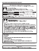
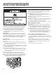
STACKED WASHER/DRYER SAFETY n It is recommended that the owner post, in a prominent location, instructions for the customer’s use in the event the customer smells gas. This information should be obtained from your gas supplier. n Post the following warning in a prominent location.
STACKED WASHER/DRYER SAFETY WARNING: FIRE OR EXPLOSION HAZARD Failure to follow safety warnings exactly could result in serious injury, death or property damage. – Do not store or use gasoline or other flammable vapors and liquids in the vicinity of this or any other appliance. – WHAT TO DO IF YOU SMELL GAS: • Do not try to light any appliance. • Do not touch any electrical switch; do not use any phone in your building. • Clear the room, building, or area of all occupants.
STACKED WASHER/DRYER SAFETY 4
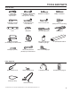
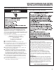
TOOLS AND PARTS Tools Needed: 8" (203 mm) or 10" (254 mm) Pipe wrench TORX T20®† Security screwdriver or bit Level 8" (203 mm) or 10" (254 mm) Adjustable wrench that opens to 1" (25 mm) Flat-blade screwdriver 1" (25 mm) Hex-head 5⁄16" Socket wrench socket wrench Phillips screwdriver Pliers (that open to 19/16" [39 mm]) Utility knife 1/4" (6 mm) Nut driver Locking pliers Caulk gun and caulk Vent clamps (for installing new exhaust vent) Pipe-joint compound suitable for gas ty
ALTERNATE PARTS AND ACCESSORIES Alternate Parts Your installation may require additional parts. If you are interested in purchasing one of the items listed here, call the toll-free number in the “If You Need Assistance” section. If You Have You Will Need to Buy Overhead sewer Standard 20 gal.
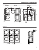
DIMENSIONS/CLEARANCES Dimensions Front View Side View 27" (686 mm) Back View 51" (1295 mm) 74" (1880 mm) 74" (1880 mm) 1 /2" 29.
STACKED WASHER/GAS DRYER INSTALLATION REQUIREMENTS Stacked Washer/Gas Dryer Location Stacked washer/gas dryer installation clearances n The location must be large enough to allow the washer and dryer doors to be fully opened. n Additional spacing should be considered for ease of installation and servicing. The doors open more than 180.° The washer door is not reversible. n Additional clearances might be required for wall, door, and floor moldings.
STACKED WASHER/GAS DRYER INSTALLATION REQUIREMENTS Stacked Washer/Gas Dryer Electrical Requirements Stacked Washer/Gas Dryer Grounding IMPORTANT: The washer/dryer must be electrically grounded in accordance with local codes and ordinances or, in the absence of local codes, with the National Electrical Code, ANSI/NFPA 70, latest edition, or Canadian Electrical Code, CSA C22.1.
STACKED WASHER/GAS DRYER INSTALLATION REQUIREMENTS Stacked Washer/Gas Dryer Gas Supply WARNING Explosion Hazard Use a new CSA International approved gas supply line. Install a shut-off valve. Securely tighten all gas connections. If connected to propane, have a qualified person make sure gas pressure does not exceed 13" (33 cm) water column. Examples of a qualified person include: licensed heating personnel, authorized gas company personnel, and authorized service personnel.
STACKED WASHER/ELECTRIC DRYER INSTALLATION REQUIREMENTS Stacked Washer/Electric Dryer Location Stacked washer/electric dryer installation clearances n The location must be large enough to allow the washer and dryer doors to be fully opened. n Additional spacing should be considered for ease of installation and servicing. The doors open more than 180.° The washer door is not reversible. n Additional clearances might be required for wall, door, and floor moldings.
STACKED WASHER/ELECTRIC DRYER INSTALLATION REQUIREMENTS Stacked Washer/Electric Dryer Electrical Requirements Washer Electrical Requirements n Do not have a fuse in the neutral or ground circuit. n This washer/dryer is equipped with a power supply cord having a 3 prong grounding plug. n To minimize the possibility of shock, the cord must be plugged into a mating, 3 prong, grounding-type outlet, grounded in accordance with local codes and ordinances.
STACKED WASHER/ELECTRIC DRYER INSTALLATION REQUIREMENTS Dryer Electrical Requirements It is your responsibility: Electric Dryer Power Supply Cord n To contact a qualified electrical installer. n To be sure that the electrical connection is adequate and in conformance with the National Electrical Code, ANSI/NFPA 70 – latest edition and all local codes and ordinances.
STACKED WASHER/ELECTRIC DRYER INSTALLATION REQUIREMENTS Dryer Direct Wire If connecting by direct wire: Power supply cable must match power supply (4-wire or 3-wire) and be: n Flexible armored cable or nonmetallic sheathed copper cable (with ground wire), covered with flexible metallic conduit. All current-carrying wires must be insulated. n 10 gauge copper wire (do not use aluminum). n At least 5 ft. (1.52 m) long.
DRYER VENTING REQUIREMENTS Elbows: ɃɃ 45° elbows provide better airflow than 90° elbows. Good Better Clamps: ɃɃ Use clamps to seal all joints. WARNING: To reduce the risk of fire, this dryer MUST BE EXHAUSTED OUTDOORS. IMPORTANT: Observe all governing codes and ordinances. Dryer exhaust must not be connected into any gas vent, chimney, wall, ceiling, attic, crawlspace, or a concealed space of a building. Only rigid or flexible metal vent shall be used for exhausting.
DRYER VENTING REQUIREMENTS Vent Hoods 4" (102 mm) Diameter Exhaust Hoods Box hood Louvered hood Exhaust hood must be at least 12" (305 mm) from the ground or any object that may be in the path of the exhaust (such as flowers, rocks, bushes, or snow). Angled hood 12" min. (305 mm) Vent System Length Maximum Vent Length/Vent Connection Maximum length of vent system depends upon the type of vent used, number of elbows, and type of exhaust hood. 3. Tighten hose clamp with Phillips screwdriver.
DRYER VENTING REQUIREMENTS If an Exhaust Hood Cannot Be Used The outside end of main vent should have a sweep elbow directed downward. 12" min. 24" min. (305 mm)* (610 mm) * Minimum clearance above any accumulation of snow, ice, or debris such as leaves If main vent travels vertically through the roof, rather than through wall, install a 180° sweep elbow on end of vent at least 2 ft. (610 mm) above surface of roof. The opening in wall or roof shall have a diameter 1⁄2" (13 mm) larger than vent diameter.
DRYER GAS SUPPLY REQUIREMENTS Type of Gas This dryer is equipped for use with natural gas. It is certified by UL for use with propane gas with appropriate conversion. No attempt shall be made to convert dryer from gas specified on serial/rating plate for use with a different gas without consulting the serving gas supplier. Conversion must be done by a qualified service technician. Gas conversion kit part numbers are listed on gas valve burner base.
INSTALLING STACKED WASHER/DRYER Remove Transport System NOTE: Slide washer/dryer onto cardboard or hardboard before moving to avoid damaging floor covering. 4. Models with separate washer power cords: Push the power cord plug into the opening on the right side of the rear panel and pull the power cord through the opening on the left side of the rear panel and close holes with the attached cap. Do not pull plug end of power cord through the right side hole.
INSTALLING STACKED WASHER/DRYER Connect Inlet Hoses Insert new hose washers (supplied) into each end of the inlet hoses. Firmly seat the washers in the couplings. Washer Connect Inlet Hoses to Washer 1. A ttach the cold water hose to the washer’s cold water inlet valve. Screw on coupling by hand until it is seated on the washer. Coupling Connect Inlet Hoses to Water Faucets Make sure the washer drum is empty. 1. Attach a hose to the hot water faucet.
INSTALLING STACKED WASHER/DRYER Route Drain Hose Proper routing of the drain hose avoids damage to your floor due to water leakage. Read and follow these instructions. 3. Once the drain hose is in place, release the pliers. Remove drain hose from the washer drum 1. Using locking pliers, squeeze hose clamp tabs together and insert over the end of the drain hose. 4. T he washer drain system can be installed using a floor drain, wall standpipe, floor standpipe, or laundry tub.
WASHER DRAIN SYSTEM The washer can be installed using the standpipe drain system (floor or wall), the laundry tub drain system, or the floor drain system. Standpipe drain system – wall or floor Laundry tub drain system The laundry tub needs a minimum 20 gal. (76 L) capacity. The top of the laundry tub must be at least 30" (762 mm) above the floor. The standpipe drain requires a minimum diameter standpipe of 2" (51 mm). The minimum carry-away capacity can be no less than 10 gal. (38 L) per minute.
ELECTRIC DRYER ELECTRICAL CONNECTIONS Electrical Connection Options If your location has: And you will be connecting to: Go to Section 4-wire receptacle (NEMA Type 14-30R) A UL Listed, Power supply cord, 120/240 V minimum, 30 A 4-wire connection dryer power supply cord* 3-wire receptacle (NEMA type 10-30R) A UL Listed, Power supply cord, 120/240 V minimum, 30 A 3-wire connection dryer power supply cord* 4-wire direct 3-wire direct 5" (127 mm) 3½" (89 mm) A fused disconnect or circu
ELECTRIC DRYER ELECTRICAL CONNECTIONS Power supply cord, 4-wire connection: 3. Connect ground wire (green or bare) of power supply cord to external ground conductor screw. Tighten screw. IMPORTANT: A 4-wire connection is required where local codes do not permit the use of 3-wire connections. A B F B D E A F C C D G E A. 4-wire receptacle (NEMA type 14-30R) B. 4-prong plug C. Ground prong D. Neutral prong E. Spade terminals with upturned ends F. 3/4" (19 mm) UL Listed strain relief G.
ELECTRIC DRYER ELECTRICAL CONNECTIONS Power supply cord, 3-wire connection: B D Use where local codes permit connecting cabinet-ground conductor to neutral wire. 1. Loosen or remove center terminal block screw. 2. Connect neutral wire (white or center wire) of power supply cord to the center terminal screw of the terminal block. Tighten screw. 3. Connect the other wires to outer terminal block screws. Tighten screws. E A C G A. 3-wire receptacle (NEMA type 10-30R) B. 3-wire plug C. Neutral prong D.
ELECTRIC DRYER ELECTRICAL CONNECTIONS Direct Wire Method Direct wire cable must match power supply (4-wire or 3-wire) and be: n Flexible armored cable or nonmetallic sheathed copper cable (with ground wire), protected with flexible metallic conduit. All current-carrying wires must be insulated. n 10 gauge copper wire (do not use aluminum). n At least 5 ft. (1.52 m) long. 1. Disconnect power. 2. Remove hold-down screw and terminal block cover. D C B A. Neutral ground wire B.
ELECTRIC DRYER ELECTRICAL CONNECTIONS Direct wire, 4-wire connection: IMPORTANT: A 4-wire connection is required where local codes do not permit the use of 3-wire connections. Direct wire cable must have 5 ft (1.52 m) of extra length so dryer can be moved if needed. Strip 5" (127 mm) of outer covering from end of cable, leaving bare ground wire at 5" (127 mm). Cut 1½" (38 mm) from three remaining wires. Strip insulation back 1" (25 mm). Shape ends of wires into a hook shape. 3.
ELECTRIC DRYER ELECTRICAL CONNECTIONS Direct wire, 3-wire connection: Use where local codes permit connecting cabinet-ground conductor to neutral wire. Direct wire cable must have 5 ft (1.52 m) of extra length so dryer can be moved if needed. Strip 3½" (89 mm) of outer covering from end of cable. Strip insulation back 1" (25 mm). If using 3-wire cable with ground wire, cut bare wire even with outer covering. Shape ends of wires into a hook shape. 1" m) (25 m 1.
ELECTRIC DRYER ELECTRICAL CONNECTIONS Optional, 3-wire connection: Use for direct wire or power supply cord where local codes do not permit connecting cabinet-ground conductor to neutral wire. 1. Remove center terminal block screw. 2. Remove neutral ground wire from external ground conductor screw. Connect neutral ground wire and the neutral wire (white or center wire) of power supply cord/cable under center terminal block screw. Tighten screw. 3.
LEVELING Leveling Stacked Washer/Dryer (cont.) 2. Grip washer/dryer from top and rock back and forth, making sure all four feet are firmly on floor. Repeat, rocking washer/dryer from side to side. If washer/dryer rocks, go to Step 3 and adjust leveling feet. If all four feet are in firm contact with floor, go to Step 4. to raise the washer/dryer. Recheck levelness of washer/ dryer and that all four feet are firmly in contact with the floor. Repeat as needed.
REVERSING DRYER DOOR SWING (OPTIONAL) Remove the Door Assembly 4. Lift the inner door assembly off outer door assembly. 1. Place a towel or soft cloth on top of dryer or work space to avoid scratching of the surface. 2. Remove three of the four screws that hold the door hinge on the front panel of the dryer. Partially loosen the remaining screw with keyhole opening and lift the door off the screw. 5. Remove four Phillips head screws to release center insert from outer door ring. 6.
REVERSING DRYER DOOR SWING (OPTIONAL) Reverse Hinge Replace the Door Assembly 1. Use a small flat-blade screwdriver to remove two plug strips from the inner door. Slide the head of the screwdriver under the plugs, without scratching the inner door surface, and lift up the strip. 1. Place the inner door assembly inside the outer door assembly. 2. Reassemble the inner and outer door assemblies with the six screws. 2. Remove the four screws that attach to inner door hinge. 3.
REVERSING DRYER DOOR SWING (OPTIONAL) 2. Remove the strike using a Phillips screwdriver. Reinstall the Door 1. Partially insert the third screw from the top, then slide the hinge onto this screw while hooking the hinge into the front panel hole. Reattach the door to the dryer front panel with the remaining three screws. 3. Insert the strike on the opposite side. 2. Check for fingerprints on the glass. Clean if necessary. 3. Close the door and verify that it latches securely.
STACKED WASHER/DRYER MAINTENANCE INSTRUCTIONS Washer Cleaning the Door Seal/Bellow To clean washer interior: 1. Open the washer door and remove any clothing or items from the washer. 2. Inspect inner glass door. If debris is present, wipe it off using a damp cloth. 3. Inspect the colored seal/bellow between the door opening and the basket for stained areas. Pull back the seal/bellow to inspect all areas under the seal/bellow and to check for foreign objects. 1.
STACKED WASHER/DRYER MAINTENANCE INSTRUCTIONS Washer Dryer Always do the following to maintain washer freshness: Maintenance instructions: n U se only “HE” High Efficiency detergent. n L eave the door slightly open after each cycle to allow for better ventilation and drying of washer interior. n C lean the washer monthly (see “To clean washer interior”), using 2/3 cup (160 mL) of liquid chlorine bleach.
ELECTRONIC CONTROL SET-UP INSTRUCTIONS Dryer control Washer control NOTE: After the washer/dryer has been installed and plugged in, the display will show “0 MINUTES” on the washer and dryer portions of the display. After the washer and dryer doors have been opened and closed, the display will show the price for both the washer and dryer. On washer/dryers set for free cycles, the display sections will flash “SELECT CYCLE.” 1.
ELECTRONIC CONTROL SET-UP INSTRUCTIONS WARM START (after power failure) – A few seconds after power is restored, if a cycle was in progress at the time of the power failure, “RESELECT CYCLE” will flash in the display, indicating the need for a key press to restart washer or dryer. WASHER DOOR LOCK – Prior to beginning a cycle, there is a door lock routine of lock/unlock/relock, then cycle begins. The door will remain locked until the end of a cycle or approximately 2 minutes after a power interruption.
ELECTRONIC CONTROL SET-UP INSTRUCTIONS Start Operating Set-Up Washer/dryers are preset at the factory and do not require any programming. However, if you want to change the settings, follow the “Set-Up Codes” guide. The first code shown in each segment is the factory default setting. The set-up code is indicated by the one or two left-hand characters. The set-up code value is indicated by the two or three right-hand characters.
ELECTRONIC CONTROL SET-UP INSTRUCTIONS If SPECIAL PRICING OPTION is selected, there is access to codes “3.XX” through “9.XX.” •P ress the lower middle (WARM) button once to advance to next code. OPTIONS 3.XX – 9.XX TO USE IF SPECIAL PRICING IS SELECTED: Code Explanation 3.06 SPECIAL CYCLE PRICE (DRYER) 3.06 Represents the number of quarters (coin 1) to start the dryer; may adjust from 0–39 (See VALUE OF COIN 1). Advance from 0–39 by pressing the upper left (COTTON/WHITES) button.
ELECTRONIC CONTROL SET-UP INSTRUCTIONS Code Explanation C. 20 VALUE OF COIN 2/ VALUE OF DRYER TOP OFF C. 20 This represents the value of coin 2 in number of nickels: 20 = $1.00. Increase between 1 and 200 nickels by pressing the middle left (COTTON/ WHITES) button, decrease by pressing the lower left (HOT) button. C. 05 9100 MODEL ONLY : For models using Enhanced Debit, this field represents the value of top off in nickels, for the dryer, or $.25. Factory default of C.05; represents 5 x $.05, or $.
WHIRLPOOL® COMMERCIAL LAUNDRY LIMITED WARRANTY IF YOU NEED SERVICE: Contact your authorized Whirlpool® Commercial Laundry distributor. To locate your authorized Whirlpool® Commercial Laundry distributor, call: 1-800-662-3587, or for web inquiries, visit www.whirlpoolcommerciallaundry.com.
W10920981B 05/18 / ® TM ©2018 Whirlpool. All rights reserved. Todos los derechos reservados.