CONSUMER SERVICES TECHNICAL L-63 EDUCATION GROUP PRESENTS 27” ELECTRIC & GAS DRYERS JOB AID Part No.
INTRODUCTION This Job Aid, “27 “ ELECTRIC & GAS DRYERS,” (Part No. 4322260), provides specific information on the installation, service and repair of Whirlpool 27” dryers. “27” ELECTRIC & GAS DRYERS” has been compiled to provide the most recent information on design, features, troubleshooting, service and repair procedures.
TABLE OF CONTENTS INTRODUCTION .................................................................................................................. II TABLE OF CONTENTS ...................................................................................................... III SECTION ONE GENERAL INFORMATION Electric Requirements .................................................................................................. 1 Exhaust Requirements for Electric and Gas Dryers .................................
SECTION FOUR TROUBLESHOOTING AND DIAGNOSIS Troubleshooting Guide .............................................................................................................23 Electronic Dryer Control Testing .............................................................................................24 SECTION FIVE TECH TIPS Wiring Diagrams ........................................................................................................................25 Strip Circuits ............................
V
Section One GENERAL INFORMATION ELECTRICAL REQUIREMENTS Electrical Requirements for Gas Dryers Important: Observe all governing codes and ordinances. Electrical ground is required on this product. ! WARNING Electrical Shock Hazard Check with a qualified electrician if you are in doubt as to whether the appliance is properly grounded. Do Not modify the power supply cord plug. If it will not fit the outlet, have a proper outlet installed by a qualified electrician.
Electrical Requirements for Electric Dryers Important: Observe all governing codes and ordinances. Electrical ground is required on this product. ! WARNING Electrical Shock Hazard Check with a qualified electrician if you are in doubt as to whether the appliance is properly grounded. Do Not modify the power supply cord plug. If it will not fit the outlet, have a proper outlet installed by a qualified electrician.
the customer to contact a qualified electrician to assure that the electrical installation is adequate and is in conformance with National Electrical Code ANSI/NFPA 70-1987 (or the latest edition) and local codes and ordinances. Important: Allow slack in the line between the wall and the appliance so that it can be move if servicing is ever necessary. A U.L.-listed strain relief must be provided at each end of the power supply cable (at the appliance and at the junction box).
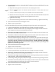
4. IF YOUR POWER SUPPLY CORD OR DIRECT WIRING HAS PLAIN WIRE ENDS, FOLLOW THESE STEPS: a. Strip outer covering back 3 inches from the end exposing the 3 wires. b. Strip the insulation back 1 inch from the end of each wire. Form the bare wire to “U” shaped hook. c. Loosen, do not remove, the center, silver-colored screw of the terminal block. d. Slide the end of the neutral (white or center) wire under the screw head with the open side of the hook on the right. Squeeze the wire together to form a loop. e.
Exhaust Requirements for Gas and Electric Dryers ! WARNING Fire Hazard Do Not use nonmetal, flexible duct. Do Not use metal duct smaller that four inches in diameter. Do Not use exhaust hoods with magnetic latches. Improper air supply for exhausting may result in a fire. Check that exhaust system is not longer than specified.
If the dryer is installed in a confined area such as a bedroom, bathroom, or closet, it must be exhausted to the outside and provisions must be made for enough air for combustion and ventilation. Check governing codes and ordinances. Also refer to the Recessed Installation Instructions. An Exhaust hood should cap the exhaust duct to prevent exhausted air from returning to the dryer. The outlet of the hood must be a least 12 inches from the ground or any object that may be in the path of the exhaust.
A. This installation must conform with American National Standard, National Fuel Gas Code ANSI Z223.1 - 1984, and local codes and ordinances. B. Input ratings shown on the rating plate (serial tag) are for elevations up to 2,000 feet, ratings should be reduced at a rate of 4% for each 1,000 feet above sea level. C. Check that this dryer is equipped with the correct burner for the particular type of gas in the home. Burner information will be found on the rating plate in the door well of the appliance. D.
c. Door is closed. d. Controls are set in running or “On” position. e. Gas shut-off valve is open on supply lines. Recessed and Closet Installation Instructions WARNING ! WARNING Potential Fire Hazard The dryer must be exhausted outside. If dryer is installed in a closet, the dryer MUST be exhausted outside. Failure to do so increases the risk of fire. This dryer may be installed in a recessed area or closet. (Fig. 5) The installation spacing is in inches and is the minimum allowable.
SECTION TWO THEORY OF OPERATION CONSOLE Fig. 6 TIMER CONTROL Electronic Dry-Miser This cycle can be used for most loads. Drying time varies according to type of fabric, size of load and dryness setting. • Set the Cycle Selector Control to the desired dryness. • Dryness is determined by an electronic moisture sensor system that “feels” the amount of moisture in the clothes as they pass over a moisture sensor mounted on the grille assembly at the front of the drum area.
Fluff Air Cycle The Fluff Air Cycle provides up to 30 minutes of unheated drying time. CLEAN TOUCH CONTROL PAD The clean touch control pad provides push button control of the following operations: TEMPERATURE SELECTION - Four levels of temperature ranging from Extra Low to High. FINISH GUARD - Allows this option to be turned On or OFF. CYCLE SIGNAL - Allows this option to be turned On or OFF. PUSH-TO-START KNOB This knob must be pushed to start the dryer. The door must be closed for the dryer to operate.
The electronic control looks at the input from the moisture sensor to see if the clothes are wet or dry. The moisture sensor will show continuity (short) if the clothes are wet and show NO continuity (open) if the clothes are dry. If the clothes are wet, the Triac on the electronic control board will block power to the timer motor, and the timer motor will not advance.
Side and Bottom Exhaust Venting Kit Side and Bottom Exhaust Venting Kits for Whirlpool 27” gas and electric dryer are available at your local parts distributor or Whirlpool Service Center. The kit contains all the materials necessary to vent the dryer out either side or through the bottom. (Fig. 10) Part No. 279818 279819 White Almond Fig.
SECTION THREE COMPONENT ACCESS CONSOLE CONTROL REPAIRS ! WARNING ELECTRIC SHOCK HAZARD Disconnect the electrical power before servicing any components. Failure to do so can result in death or electrical shock. Note : Potential floor damage. Slide dryer onto cardboard or hardboard before moving across floor. Failure to do so may damage floor covering. Removing the Console 1. Remove the two screws at the base of the console. (Fig.11) 2. Grab console on both sides.
Removing the Timer 1. Pull the timer knob off the timer assembly shaft. 2. Tip the console into the service position. 3. Disconnect the wiring harness connectors from the timer assembly terminals. 4. Remove the two (2) screws securing the timer assembly mounting bracket to the console. Removing the Clean Touch Switch Assembly Mounting “EARS” 1. Tip the console into the service position. 2. Disconnect the wiring harness leads from the terminals on the switch assembly. 3.
5. Slide top across dryer so that rear is under back brackets and front fits into front clips. 6. Reinstall three dryer top screws. 7. Close console. 8. Reinstall the two console screws. Fig. 16 Replacing the Drum Lamp 1. Open dryer door. Remove the drum lamp cover screws. (Fig. 17) 2. Lift and slide off the drum lamp cover. 3. Tip the light socket forward and remove the bulb. (Fig. 18) 4. Put new bulb into place. 5. Slide drum light cover back into place. Reinstall the drum light cover screw.
Replacing the Blower Wheel 1. Open dryer door and remove lint screen. (Fig. 20) Close the dryer door. Fig. 20 2. Remove two (2) screws from lint duct and remove the lint duct. 3. Remove two (2) screws from blower housing cover and remove blower housing cover. (Fig. 21) Fig. 21 4. Reach behind the blower housing and place a 7/8’’ open end wrench on the motor. (Fig. 22) Rotate the blower wheel clockwise to lock the motor shaft with the wrench. Allow wrench to lock against the motor bracket. 5.
Replacing the Motor 1. Remove the blower housing. 2. Remove two screws mounting motor in place. (Fig. 25) 3. Reach under drum and push idler pulley to the left to release tension on the belt. (Fig. 26) Remove belt from motor pulley. Fig. 25 4. Slide motor to right, out of slots, and pull forward out of dryer. (Fig. 27) 5. Disconnect motor wiring harness. (Fig. 28) Remove idler pulley assembly and broken belt switch and place on new motor. Fig. 26 6. Connect new motor wiring to motor wiring harness. 7.
Replacing the Heating Element (Electric Dryers) 1. Remove the screw from heat shield. (Fig. 31) Remove the wires to the heat element. 2. Remove the screw from side of heater box (Fig. 32) and slide the heat element out of dryer. 3. Slide new heat element into dryer and reattach screw on side of heater box. Fig. 31 Fig. 32 4. Reattach the heat element wires. Replace heat shield. Removing the Burner Assembly (Gas Dryers) 1. Turn off the gas supply to the dryer. 2.
Removing the Dryer Door 1. Remove the toe panel. 2. Pull down and unhook and remove the left and right door springs. (Fig. 36) 3. Open dryer door. Remove the screws from each door hinge. (Fig. 37) Remove dryer door by sliding it off of hinges. 4. Slide new door onto hinges. Align screw holes in hinges. Reinstall hinge screws into new dryer door. Close dryer door. 5. Hook long, skinny end of door spring into left hinge. Pulling down on spring, hook other end into bottom front of cabinet.
Removing the Belt and the Drum 1. Remove the front panel. 2. Reach underneath drum and behind motor to locate idler pulley. Push idler pulley to left to release drum belt tension. Remove the belt from the motor pulley. (Fig. 41) 3. Remove the drum and belt from the cabinet. (Fig. 42) Fig. 41 Fig. 42 Replacing the Front Support Rollers and Shafts 1. Remove the front panel. 2. Remove the tri-ring and the support rollers. (Fig. 43) Using a 9/16’’ open end wrench, remove the support roller shaft.
Removing the Rear Bulkhead Assembly 1. Remove the front panel. 2. Reach underneath drum to locate idler pulley. Push idler pulley to left to release drum belt tension. Remove belt from motor pulley. Remove the drum from dryer. 3. Remove heat source assembly (burner assembly and funnel or heat element and duct). 4. Move dryer so you can easily remove back of dryer. 5. Starting with screw (A), remove in order screws (A), (B), (C), (D), (E), (F), and (G) from back of dryer. (Fig. 45) 6.
-- NOTES -- 22
SECTION FOUR TROUBLESHOOTING and DIAGNOSIS TROUBLESHOOTING GUIDE CONDITION Dryer will not run. POSSIBLE CAUSE SOLUTION No power to unit. Door switch not making. Thermal fuse open. Broken belt or belt switch. Check voltage supply. Check door switch siring and continuity. Check fuse continuity. Check for broken belt or check belt switch for continuity. Check timer contacts for continuity. Check voltage to motor, contacts 4 & 5, (120VAC). Check motor windings for continuity, (2-4 ohms).
“C” VERSION ELECTRONIC DRYER CONTROL Component Testing There is no reliable electrical check that can be made on the electronic control board. Do not attempt to replace any components on the electronic control board. The following tests will isolate problems with the electronic control board and other related components. (Fig. 48) NOTE: Check all wiring and connections and perform the following tests before attempting to replace the electronic control board. Timer Shuts Off but Clothes are Still Damp 1.
SECTION FIVE TECH TIPS WIRING DIAGRAM Electric Dryer 25
WIRING DIAGRAM Gas Dryer 26
TIMER SCHEDULE TIMER SCHEDULE SWITCH CONTACTS GY-WB BK-BU-V BK-BU BK-R T-BY T-W AUTOREGULAR AUTO-SOFT/ LOW HEAT TIMER POSITION COOL DOWN END OF & AIR DRY CYCLE 123456789012 123456789012 123456789012 123456789012 LEGEND TIMEDTIMED-SOFT/ REGULAR LOW HEAT GUARD 1234567890 1234567890123 1234567890 1234567890123 1234567890 1234567890123 1234567890 1234567890123 123456789012345678 1234567890123 123456789012345678 123456789012345678 1234567890123 123456789012345678 1234567890123 1234567890 123456789012 12
3. Temperature Control Circuit - Thermostat heater ENERGIZED 4. Electric Heater Element Circuit - Heater element ENERGIZED. 5. Gas Burner Circuit - Burner assembly ENERGIZED. 6.
7. Buzzer Circuit - Timer contacts OPEN 8. Drum Lamp Circuit - Lamp LIT. 9. Timer Motor Circuit - Timed dry cycle. 10. Timer Motor Circuit - Automatic dry cycle.
MODEL/SERIAL NUMBER PLATE LOCATION The model/serial number plate for the Whirlpool brand 27” DRYER is located on the left side of the front panel inside the door opening. (Fig. 49) Fig.
CORPORATION PB