INSTALLATIONINSTRUCTIONS COMMERCIALSTACKEDDRYER Gas (12(!-Volt,60-Hz)or Electric (12(}/24(}-Volt, 60-Hz) Table of Contents ........................................................ 2 Actual unit may or may not contain doors with windows depending on model 8577211 www,whirlpool.
TABLEOF CONTENTS DRYER SAFETY ............................................................................ 2 iNSTALLATiON REQUIREMENTS 4 .............................................. Location Requirements .............................................................. Tools and Parts .......................................................................... 4 5 Electrical Requirements 6 ............................................................ Gas Supply Requirements ..........................
WARNING: For your safety, the information the risk of fire or explosion, in this manual or to prevent property = Do not store or use gasoline or any other appliance. or other flammable = WHAT TO DO iF YOU SMELL GAS: must damage, be followed personal to minimize injury, or death. vapors and liquids in the vicinity of this • Do not try to light any appliance. • Do not touch any electrical switch; do not use any phone in your building. • Clear the room, building, or area of all occupants.
INSTALLATIONREQUIREMENTS 'iii_i::_ ¸0 !_!i_ iiii_i_ ii__i!iiiii J_' _iii _'_i: _!ii_ Gather the required tools and parts before starting installation. Read and follow the instructions provided with any tools listed here. Tools needed [] 8" or 10" pipe wrench [] [] 8" or 10" adjustable wrench Flat-blade screwdriver [] Phillips screwdriver Explosion Hazard [] Adjustable wrench that opens to 1" (2.5 cm) or hex-head socket wrench Keep flammable materials and vapors, such as gasoline, away from dryer.
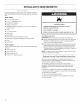
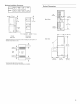
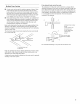
Minimum Installation Clearances Recessed Closet Back 0 in (0 cm) 0 in (0 cm) Sides 0 in (0 cm) 0 in (0 crn) Top 6 in (15.2 cm) 0 in (0 cm) Product Dimensions Front -7 in (17.5 cm) top exhaust ,_- _ 0" (0 cm! -- m 13-1/2" (34.3 cm) t Back View I u_ O_ I (o cm) 6_ (15.2 cm) 41" (104.1 cm) O \ _ 0 closet door exhaust bottom...... 7" (17.8 cm) o 0cm l' Closet side view 27" (68.
IMPORTANT: The dryer must be electrically grounded in accordance with local codes and ordinances or, in the absence of local codes, with the National Electrical Code, ANSI/NFPA 70, latest edition. The National Electric Code requires a 4-wire supply connections for homes built after 1996, dryer circuits involved in remodeling after 1996, and all mobile home installations.
i!!iii,, i:iiiiii i!!:iiiieqxiiX', (!;z iiF !! isesi: Gas Supply Recommended Line method [] Provide a gas supply line of rA" rigid (IPS) pipe to the dryer location. Pipe joint compounds that resist the action of LP gas must be used. Do not use TEFLON _ tape. With LP gas, piping or tubing size can be 1/2"minimum. Usually, LP gas suppliers determine the size and materials used in the system. Alternate method [] Explosion Hazard Use a new CSA international approved gas supply line.
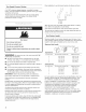
Plan installation to use the fewest number of elbows and turns. Gas Supply Pressure Testing A 1/s"NPT minimum plugged tapping, accessible for gauge testing, must be installed immediately upstream of the gas supply connection to the dryer. The dryer must be disconnected from the gas supply piping system during any pressure testing of the system at test pressures in excess of 1/2psig. ExhaustAir Flow A. Better B. Good Allow as much room as possible when using elbows or making turns.
if an exhaust hood cannot be used: Multiple Dryer Venting [] A main vent can be used for venting a group of dryers. Main vent should be sized to remove 200 CFM of air per dryer. Large-capacity lint screens of proper design may be used in the main vent if checked and cleaned frequently. The room where the dryers are located should have make-up air equal to or greater than the CFM of all the dryers in the room. [] Back-draft Damper Kits, Part No.
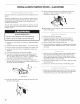
INSTALLATION INSTRUCTIONS - GASDRYER 9° The collar houses the accumulator timer with actuating arm and button. Secure coin slide mechanism from inside the control panel using the 3/16"bolt and washer included with the slide mechanism. Install coin box. The factory-installed timer is set to provide 45 minutes (4 pins) of drying time when activated by the coin slide. Timer cams for 30-minute (6 pins) and 60-minute (3 pins) drying times are included in the parts bag.
3. Check dryer operation (some accumulated the timer due to factory testing). time may be on Insert coins in slide and press slide in slowly. (Operating time will accumulate per number of coins and type of timing cam used.) Push START/RESTART button. Using a full heat cycle (not the air cycle), let the dryer run for at least five minutes. Dryer will stop when time is used up. NOTE: Dryer door must be closed for dryer to operate. When door is open, dryer stops, but timer continues to run.
2. Remove hold-down screwandtheterminal blockcover. Power Supply Cord Method _D This dryer is manufactured with the neutral ground wire connected to the neutral (center) of the wiring harness at the terminal block. If local codes do not permit this type of connection, use "Four-wire connection" instructions. A. External ground conductor screw B. Tab Use a UL-listed power supply cord rated 240-volt min., 30-amp and marked for use with a clothes dryer. C. Terminal block cover D.
Power Supply Cord, Three=wire electrical connection: Use this method where local codes permit connecting neutral ground wire to neutral wire: A .................... I_] 5. Loosen or remove the center terminal F-'__ block screw. F ...... 0 Connect the neutral wire (white or center) of the power supply cord to the center, silver-colored terminal screw of the terminal block. Tighten screw. 7. E _ ............ Connect the other wires to outer terminal 8. Tighten strain relief screws. 9.
j A. Extemat ground conductor screw B. Tab C. Terminal block cover D. Hold-down screw Fire Hazard Use 10 gauge solid copper b wire. Use a UL listed strain relief. 3= Disconnect power before making electrical connections. Connect neutral wire (white or center wire) to center terminal (silver).
Direct Wire, Three=wire electrical connection: Use this method where local codes permit connecting neutral ground wire to neutral wire: 5. Loosen or remove the center terminal block screw. 6. Three wire with ground wire: green or bare wire cut short. Wire is not used. Dryer is grounded through neutral conductor. Place the hooked end of the neutral wire (white or center) of the direct wire cable under the center screw of the terminal block (hook facing right). Squeeze hooked end together.
CHANGINGTO A 30-OR60-MINUTETIMINGCAM 5= Insert a narrow, flat-blade screwdriver under the timing cam near the clock shaft. Gently lift cam straight up and off shaft making sure that the V-shaped notch clears the ratchet tooth. _ili.. • Electrical Disconnect Shock Hazard power before making cam changes. Failure to follow these instructions or electrical shock. can result in death You can install the 30-minute or 60-minute timing cam (shipped with dryer) as follows: t. i_ B. Timingcam C. Drivelug D.