240Edwards Street.SE C]eveiand. Tennessee _7211 Tel:423-,-t72-3333 Fax:423-473-6710 GAS INSTALLATION MANUAL SEALED TOP BURNERS 30" WIDE SELF-CLEAN FREESTANDING INSTALLER: AND SLIDE-IN-RANGES LEAVE THESE INSTRUCTIONS WITH THE APPLIANCE. PLFASE KEEP THIS MANUAL FOR FUTURE REFERENCE. This manual is intended to assist in the initial installation and adjustments of the range. YOUR RANGE MAY NOT BE EQUIPPED WITH SOME OF THE FEATURES REFERRED TO IN THIS MANUAL.
40E(;war_s Street,SE C',eveiand, Tannessee 37311 Tel:423-472-_333 Fax: _23-._78-_71D SECTION 1 INSTALLATION A. SERVICE - PARTS INFO1LMATION WHEN YOUR RANGE REQUIRES SERVICE OR REPLACEMENT PARTS, CONTACT YOUR DEALER OR AUTHORIZED SERVICE AGENCY. PLEASE GIVE THE COMPLETE MODEL AND SERIAL NUMBERS OF THE RANGE WHICH IS LOCATED ON THE RANGE MODEL NUMBER PLATE. NOTE: THE RANGE MODEL NUMBER PLATE IS LOCATED ON THE LOWER FRONT FRAME OF THE RANGE. B. CODES.
Customer Ser',rica __ 248Edwards Street,SE C]e,:e]and. Tennessae 37311 Te;::;23-472-,3.
240 EdwardsStreet,SE CEeveiand, Tennessee37311 Tet: 423472-3333 Fax::t23-478-67;O or smoke damage should the packing material ignite. NOTE: A range should NOT be installed directly over kitchen carpeting unless an insnladng pad or I/4" thick piece of plywood is placed between the range and carpet.
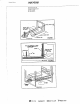
_ustomerService ..__ 240_c.wards Street.SE CleveJand. Tennessee 3731 Tei:a22-_.72-3333 Fax:a23-478-_0 available). Secure the ANTI-TIP bracket to the floor with the two screws provided. Proceed to Step 3. 2. Wall: Locate the center of the two holes identified in figure I as "WALL-PLATE'. Drill an angled 1/8" pilot hole in the center of each hole as shown in figure 2. (A nail or awl may be used if a drill is not available).
248 EdwardsStreet,SE Cleveland,Tennessee37,311 Tel: 423-J72-3333 Fax:_t23-478-BTtO GUn-E • 1/4 N M_ F . / PLATE ,_, ,=,,-7,, F]GURE2 , 11]; ._.'_TA6 Admiral71 _E._N-_ _aejic C..
Cu,_0mer _r_ice A0t][A'_.r_/_G 2aOEdwards Street,SE C1evelanar Tennessee ,37311 Tei:423-472-3323 Fax:423-478-571 [3 F. CONNECTING THE RANGE 1. ELECTRICAL SUPPLY CONNECTION: The range requires 120 volts, 60 cycle alternating current from an outlet capable of supplying I5 amperes. WARNING: ELECTRICAL GROUNDING INSTRUCTIONS. This appliance is equipped with a three-prong grounding plug for your protection against shock hazard and should be plugged directly into a properly grounded receptacle.
240Eawa_s S[reet SE C_e_eian_, Tennessee37311 Te!:422472-23S3 Fa×:a23-_78-67iO j. Adjust burner air shutter to the widest opening that will not cause the flame to lift or blow off the burner when cold. NOTE: Correctly adjusted sealed burners will blow off without a pot over the burner. could be adjusted with a pot in place. FIGURE Regulator 4 L,j These "_"_"_ & Connection G.
240Edwaras Street,SE C',eveland, Tennessee 37311 Tel:423-472-2333 Fax:.222-,.t78-87!0 H. CHECKING PRESSURE OF HOUSE PIPING SYSTEM 1. The appliance and its individual shutoff valve must be disconnected from the gas supply piping system during any pressure testing of that system at test pressures in excess of 1/2 pound/sq, in. (3.SkPa) (13.8 in. water column). 2.
2_0Edwards Street SE C',evelan& Tennessee 37311 Te!:-123-a72-3333 F_x:423-478-87i0 SECTION II RANGE ADJUSTMF.NTS A. TOP SECTION - ELECTRIC IGNITION To operate, push andturn top burner knob to the LITE position. The top burner will light. To turn OFF spark after the top burner has ignited: 1. For ranges with SINGLE purpose valves, turn knob to the right, clockwise to the HI setring, figure 6A. 2. For ranges with HI-SIM-WARM valves, turn knob, either direction to HI setting, figure 6B.
240Edwards Street.SE Cleveland. Tennessee $73IT Tel:423-472-3333 Fax:4.23-478-67_Q OFF. The burner flame will go "out" in 20 to 30 seconds after the ignitor goes "OFF". To maintain any given oven temperature this cycle will continue as long as the dial (or display) is at the given temperature. b. In case servicing should become necessary, a manual gas valve is supplied on the pressure regulator to shut off the gas to the oven and broiler burner only. (See figures 3 and 4). c.
2_.0EdwardsStreet. SE Cleveland,Tennessee37311 Tel: 423-472-3332 Fax:_.23-478-6710 c. The air shutter adjustments are the same as illustrated in figure 8. The approximate length of the flame of the broil burner is a distinct inner blue flame of 3/8 inch. The outer flame will extend outward as a sheet of flame adjacent to the burner baffle (flame spreader) above the broil burner, figure 9. The air shutter, figure 8 should be set to full open on both natural and on LP gas. d.
240Edwards StresI.SE C_eveland. Tennessee 27311 Tei:423-472-3333 Fax:423-478-571G SECTION IH GAS CONVERSION A. GENERAL All sealed burner ranges and cooktops are equipped with double coaxial (universal) orifices and with a convertible gas regulator. The unit model number plate states which gas it was adjusted for at the factory.
240Edwards Street.SE Uevetand, Tennessee 3731_ Te]:a22-_72-3233 Fax:423-478-a710 Reinstall cap nut to regulator and replace dust cover. "CAUTION" be sure marking for the type of gas to which regulator has been converted is visible in top of cap nut before replacing plastic dust cover. See figure 11. 3. Remove cap and forcibly snap out plastic plunger from bottom of cap. Turn plunger over and forcibly snap back in origina/location (figure 12).
24(]Edwar6s Street.SE C!eve[an_, Tennessee 37311 Te_:J22-472-3333 Fax:423-,,t' 7_,-_710 2. FROM LP GAS TO NATURAL GAS: a.Place burner wrench (part number 8002P026-60, available from you dealer or authorized service agency) over surface burner assembly with ignitor positioned inside gap in wrench ring (figure 13A). This prevents ignitor from being crushed when wrench tightens on burner assembly. Rotate burner assembly approximately one-eighth turn counter-clockwise and lift from top (figure 13B).
240E_ardsStreeLSE Cleve!and. Tennessee 37311 Tei:423-_72-3333 Fa×:_23_478-57W D. TOP BURNER "WARM" ADJUSTMENT If equipped with a single purpose valve (see figure 15) no adjustment is required. If equipped with HI, SIM, WARM valves, the burner flame at the WARM position should extend to the outer edge of the lip of the burner cap. The WARM setting should be such that a stable flame is maintained on the burner when turning the knob from HI to WARM.
Z4OEdwards Stmet,SE C;eve[and, Tennessee 3733; Teh42S-472-3233 £ax:_23-478-5710 SECTION IV INSTALLATION FREE STANDING DRAWINGS RANGES Range may be installed with zero inches clearance adjacent to (against) combustible construction at the rear and on the sides below the cooktop. For clearance for wail cabinets above a free-standing conventional range cooktop see illustration and dimensions given below. Wall cabinets can be installed above and adjacent to a range, with elevated oven as illustrated.
240Edwards Street.SE Cleveland, Tennessee 2731: Tel:423472-3333 Fax:4_3-478-6710 TABLE NO. I DIMENSION A WIDTH OF RANGES DIMENSION B NO LESS THAN WIDTH OF RANGES DIMENSION O 30" Free Standing, Self Clean 30 "°` 30" 3" Rgure 19B 30" Slide-in, Self Clean 30"** 30" 3_o F_gure19C RANGE SERIF-.SNUMBER FOR DIMENSIONS LOWER OABINL¢:% " DEPTH & CUTOUT A, B & C- SEE TABLE NO.
24GEcwarosStr_e[,SE Cleveiane,Tennessee37311 TeL_23472.3323 Fax:_23478-6710 WAL_ • _ RL_4 ¢O_L£T_ RGURE _-" f _ COOK TOP. "-...J ' _ aE El IN. 198 Gas Free-Standing Ranges OVEN I BRCILER 1 CUTOUT DIMEHSIONS APPROX. SHIPPfNG NOLO: 5--TI_.ORKKOII_C¢_R0 _--.-/ RGURE 10 ¢_,F.JI, R TO_, X-"--..- 19C Gas $lide-_n Ranges OVEI,I I , W1°TIt BROILER H_IGWr I CUTOUT DIMENSIONS SHIPPING APPROX.