
Installation manual


240Eawa_s S[reet SE
C_e_eian_,Tennessee37311
Te!:422472-23S3
Fa×:a23-_78-67iO
j. Adjust burner air shutter to the widest opening that will not cause the flame to lift or blow
off the burner when cold.
NOTE: Correctly adjusted sealed burners will blow off without a pot over the burner. These
could be adjusted with a pot in place.
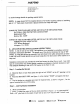
FIGURE 4 L,j "_"_"_
Regulator & Connection
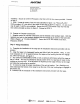
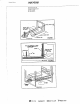
G. CHECKING MANIFOLD GAS PRESSURE
If it should be necessary to check the manifold gas pressure, remove right rear burner
assembly by placing a burner wrench (part number 8002P026-60, available from your dealer
or authorized service agency ) over surface burner assembly with ignitor positioned inside
gap in wrench ring (figure 5A). This prevents ignitor from being crushed when wrench
tightens on burner assembly. Rotate burner assembly approximately one-eighth turn coun-
terclockwise and lift from main top (figure 5B). Connect manometer (water gauge) or other
pressure device to the top burner right rear orifice hood, using a rubber hose with inside
diameter of approximately 1/4", hold tubing down tight over orifice hood. Turn burner on.
For an accurate pressure check have at least two (2) other top burners burning. Be sure the
gas supply (inlet) pressure is at least one inch (1 ") above specified range manifold pressure.
The gas supply pressure should never be over 14 inches water column. When properly
adjusted for Natural Gas the water column pressure is 4_, for LP Gas the water column
pressure is 10". Replace burner assembly in main top and rotate approximately one-eighth
turn clockwise using burner wrench until burner locks into position with ignitor facing rear-
ward.
FIGURE5A
FIGURE_5B
_ _MAYrAG &dmtral _'! re,dE N N -,i_dl_ _Ji_ C,._ef