® ® ELECTRONIC GAS DRYER Use & Care Guide In the U.S.A., for questions about features, operation/performance, parts, accessories or service call: 1-800-253-1301 or visit our website at... www.whirlpool.com Table of Contents ....................................................
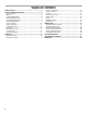
TABLE OF CONTENTS DRYER SAFETY..............................................................................3 INSTALLATION INSTRUCTIONS ..................................................5 Tools and Parts ............................................................................5 Options .........................................................................................5 Location Requirements ...............................................................6 Electrical Requirements ....................
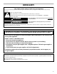
DRYER SAFETY Your safety and the safety of others are very important. We have provided many important safety messages in this manual and on your appliance. Always read and obey all safety messages. This is the safety alert symbol. This symbol alerts you to potential hazards that can kill or hurt you and others. All safety messages will follow the safety alert symbol and either the word “DANGER” or “WARNING.
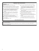
IMPORTANT SAFETY INSTRUCTIONS WARNING: To reduce the risk of fire, electric shock, or injury to persons when using the dryer, follow basic precautions, including the following: ■ ■ ■ ■ ■ ■ ■ ■ Read all instructions before using the dryer. Do not place items exposed to cooking oils in your dryer. Items contaminated with cooking oils may contribute to a chemical reaction that could cause a load to catch fire.
INSTALLATION INSTRUCTIONS Tools and Parts Check that you have everything necessary for correct installation. Proper installation is your responsibility. ■ 8" or 10" pipe wrench ■ Knife ■ 8" or 10" adjustable wrench (for gas connections) ■ Safety glasses ■ Vent clamps ■ Pipe-joint compound resistant to L.P. gas ■ Caulking gun and compound (for installing new exhaust vent) ■ Gloves ■ Pliers ■ Flat-blade screwdriver ■ Adjustable wrench that opens to 1" (2.
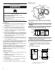
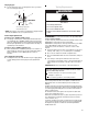
Dryer Dimensions Location Requirements 51½" (130.81 cm) WARNING 38" (96.52 cm) Explosion Hazard Keep flammable materials and vapors, such as gasoline, away from dryer. *31½" (80 cm) Place dryer at least 18 inches (46 cm) above the floor for a garage installation. Failure to do so can result in death, explosion, or fire. 27" (68.6 cm) *Most installations require a minimum 5½" (14 cm) clearance behind the dryer for the exhaust vent with elbow. See “Venting Requirements.
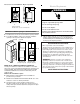
Recessed or closet installation - Dryer on pedestal Electrical Requirements 14" max. (35.6 cm) WARNING 18" min. (45.72 cm) 0" (0 cm) 27" (68.6 cm) 0" (0 cm) 0" (0 cm) A Electrical Shock Hazard 0" 31½" (80 cm) (0 cm) Plug into a grounded 3 prong outlet. B Do not remove ground prong. A. Recessed area B. Side view - closet or confined area Do not use an adapter. Do not use an extension cord. Failure to follow these instructions can result in death, fire, or electrical shock.
■ Gas Supply Requirements WARNING Must include a shutoff valve: An individual manual shutoff valve must be installed within six (6) feet (1.8 m) of the dryer in accordance with the National Fuel Gas Code, ANSI Z223.1. The location should be easy to reach for opening and closing. C A B Explosion Hazard Install a shut-off valve. Securely tighten all gas connections. Examples of a qualified person include: licensed heating personnel, authorized gas company personnel, and authorized service personnel.
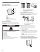
Dryer gas pipe ■ Venting Requirements The gas pipe that comes out through the rear of your dryer has a ³⁄₈" male pipe thread. WARNING B *6¼" (15.9 cm) Fire Hazard 1½" (3.8 cm) A Use a heavy metal vent. Do not use a plastic vent. A. ½" NPT gas supply line B. ³⁄₈" NPT dryer pipe Do not use a metal foil vent. Failure to follow these instructions can result in death or fire. *NOTE: If the dryer is mounted on a pedestal, the gas pipe height must be an additional 13" (33 cm) from the floor.
Plan Vent System Typical exhaust installations Typical installations vent the dryer from the rear of the dryer. Other installations are possible. B A C A D E F G A. Standard rear offset exhaust installation B. Left or right side exhaust installation C. Bottom exhaust installation (Not an option with pedestal installations.) B C Alternate installations for close clearances H Venting systems come in many varieties. Select the type best for your installation.
Determine Vent Length Vent Length Chart 1. Select the route that will provide the straightest and most direct path outdoors. Plan the installation to use the fewest number of elbows and turns. When using elbows or making turns, allow as much room as possible. Bend vent gradually to avoid kinking. Avoid 90º turns when possible. Number of 90º turns or elbows Type of vent Box or Louvered hoods Angled hoods 0 Rigid metal Flexible metal 64 ft (20 m) 36 ft (11 m) 58 ft (17.7 m) 28 ft (8.
For mobile home use Install Leveling Legs Gas dryers must be securely fastened to the floor at the time of installation. WARNING Excessive Weight Hazard Use two or more people to move and install dryer. Failure to do so can result in back or other injury. 1. To protect the floor, use a large flat piece of cardboard from the dryer carton. Place cardboard under the entire back edge of the dryer. See illustration. 2. Firmly grasp the body of the dryer (not the console panel).
A combination of pipe fittings must be used to connect the dryer to the existing gas line. Shown following is a recommended connection. Your connection may be different, according to the supply line type, size and location. D A B C A. ³⁄₈" flexible gas connector B. ³⁄₈" dryer pipe C. ³⁄₈" to ³⁄₈" pipe elbow D. ³⁄₈" pipe-to-flare adapter fitting 3. Open the shutoff valve in the supply line. The valve is open when the handle is parallel to the gas pipe. A B A. Closed valve B. Open valve 4.
DRYER USE More Less Starting Your Dryer WARNING 2. Place laundry in dryer and shut door. See “Loading.” 3. Rotate the dial to select either an Automatic or Manual Cycle then press the CONTROL ON button. The preset settings and drying time for the cycle chosen will be displayed. To use an Automatic Cycle ■ Point the dial to an Automatic Cycle. ■ Select DRYNESS LEVEL to adjust how dry you want the load to be. The time displayed is an estimated length of the cycle based on the Dryness Level selected.
To use a Manual Cycle ■ NOTE: The More Time or Less Time feature can be used only with Manual Cycles. ■ Press TEMPERATURE until the desired temperature glows. NOTE: Pressing the Dryness Level button will cause the triple beep indicating that this option is not selectable. Also, a Dryness Level is not indicated. ■ Control Locked Rotate the dial to select a Manual Cycle. Press MORE TIME or LESS TIME until the desired drying time is displayed.
Drying and Cycle Tips Status Lights Select the correct cycle and dryness level or temperature for your load. If an Automatic Cycle is running, the display shows the estimated cycle time when your dryer is automatically sensing the dryness level of your load. If a Manual Cycle is running, the display shows the exact number of minutes remaining in the cycle. Cool Down tumbles the load without heat during the last few minutes of all cycles. Cool Down makes the loads easier to handle and reduces wrinkling.
Automatic Preset Cycle Settings Cycles Select the drying cycle that matches the type of load you are drying (see Automatic Preset or Manual Preset Cycle Settings charts). Cycle control knob Automatic Cycles Automatic Cycles allow you to match the cycle to the load you are drying. See the following “Automatic Preset Cycle Settings” chart. Each cycle dries certain fabrics at the recommended temperature. A sensor detects the moisture in the load and automatically adjusts the drying time for optimal drying.
When using Air Only Additional Features WRINKLE SHIELD™ Feature When you are unable to remove a load of clothes from the dryer as soon as it stops, wrinkles can form. The WRINKLE SHIELD™ feature periodically tumbles, rearranges and fluffs the load to avoid wrinkles. ■ Press the WRINKLE SHIELD™ feature to get up to 120 minutes of heat-free, periodic tumbling at the end of a cycle. ■ Stop at any time by pressing the WRINKLE SHIELD™ feature or opening the dryer door.
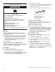
3. Put the wet items on top of the rack. Leave space between the items so air can reach all the surfaces. NOTE: Do not allow items to hang over the edge of the rack. DRYER CARE Cleaning the Dryer Location Keep dryer area clear and free from items that would obstruct the flow of combustion and ventilation air. WARNING 4. Close the door. 5. Select a timed drying cycle and temperature, or an air cycle (see following chart).
As needed cleaning Laundry detergent and fabric softener residue can build up on the lint screen. This buildup can cause longer drying times for your clothes, or cause the dryer to stop before your load is completely dry. The screen is probably clogged if lint falls off the screen. Clean the lint screen with a nylon brush every 6 months, or more frequently, if it becomes clogged due to a residue buildup. To wash 1. Roll lint off the screen with your fingers. 2. Wet both sides of lint screen with hot water.
TROUBLESHOOTING First try the solutions suggested here and possibly avoid the cost of a service call... Dryer displaying code message ■ “PF” (power failure), check the following: Was the drying cycle interrupted by a power failure? Press (and hold) HOLD TO START button to restart the dryer. ■ “E” Variable (E1, E2, E3) service codes: Call for service.
Odors ■ Garment damage Have you recently been painting, staining or varnishing in the area where your dryer is located? If so, ventilate the area. When the odors or fumes are gone from the area, rewash and dry the clothing. ■ Check the following: Were zippers, snaps, and hooks left open? Were strings and sashes tied to prevent tangling? Were care label instructions followed? Were items damaged before drying? ASSISTANCE OR SERVICE Before calling for assistance or service, please check “Troubleshooting.
Notes 23
WHIRLPOOL CORPORATION MAJOR APPLIANCE WARRANTY ONE YEAR LIMITED WARRANTY For one year from the date of purchase, when this major appliance is operated and maintained according to instructions attached to or furnished with the product, Whirlpool Corporation or Whirlpool Canada LP (hereafter “Whirlpool”) will pay for FSP® replacement parts and repair labor to correct defects in materials or workmanship. Service must be provided by a Whirlpool designated service company. ITEMS WHIRLPOOL WILL NOT PAY FOR 1.